Clutch Hose Failure, Replacement and Maintenance Guide | VADEN
Clutch hose symptoms, swelling test, step-by-step replacement, torque values and maintenance tips for heavy commercial vehicles — VADEN technical guide.
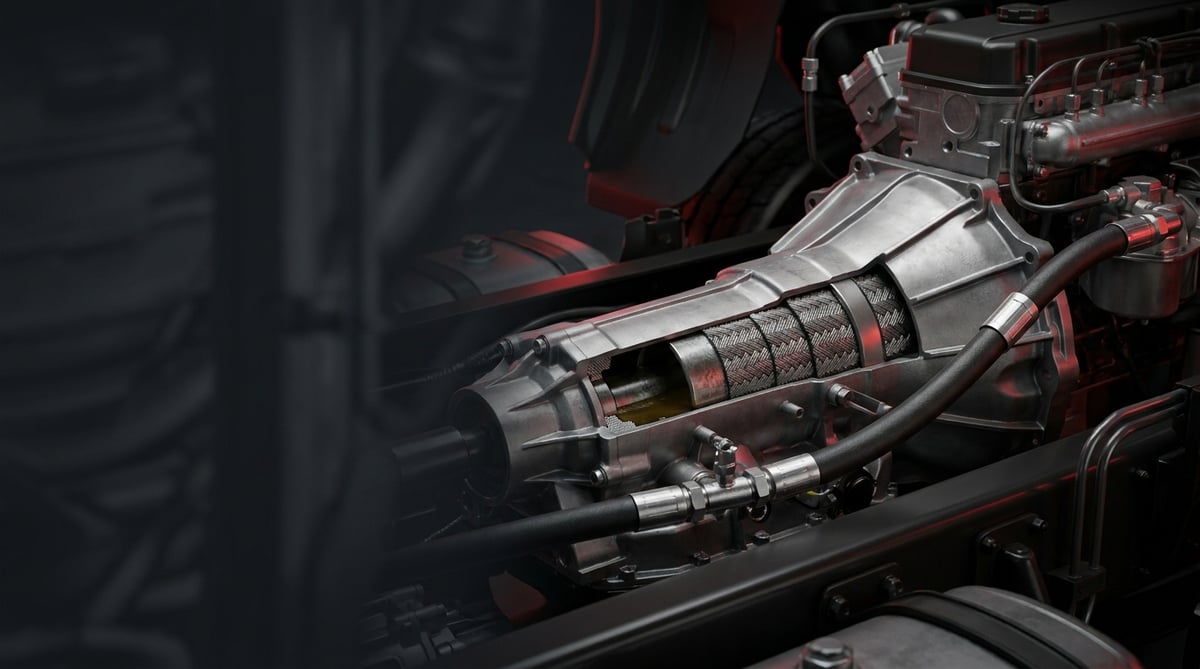
The driver presses the clutch, the pedal sinks lower than usual and the gear engages only with force. On a hill start the clutch does not disengage fully and the gearbox rattles. When the vehicle arrives at the workshop, the first place inspected is usually the pressure plate and disc set; yet the source of the fault is often a far smaller and far cheaper component: the clutch hose. On a heavy commercial vehicle the clutch control runs through a flexible line that reaches from the master cylinder to the slave cylinder or to the clutch servo. If that line swells, balloons internally or develops a micro leak, the force applied at the pedal cannot be transmitted to the system in full. This guide covers the clutch hose in workshop language: what it does, how it fails, how its symptoms differ from a worn pressure plate and disc, how it is replaced and how its service life can be extended.
E-E-A-T note: This document was prepared by the VADEN technical team on the basis of field and product experience with heavy commercial vehicle clutch control systems. The values given here are typical reference ranges; they vary according to vehicle family, control architecture and year of manufacture. For exact torque, pressure and clearance values always refer to the vehicle manufacturer's current service manual. Last updated: July 2026.
Component sizing is based on the relevant international standard family (ISO/EN/DIN/SAE) and the manufacturer OE specification.What Is a Clutch Hose? Function and Operating Principle
The clutch hose is the reinforced flexible connecting element that sits between the fixed metal lines of the clutch control system and the moving components on the engine/gearbox, transmitting hydraulic pressure (in some applications compressed air) leak-free while flexing.
The operating logic becomes clear when the system is viewed as a whole. When the pedal is pressed, the clutch master cylinder pressurises the hydraulic fluid. This pressure travels through the fixed pipework and the flexible hose to the slave cylinder, or to the pneumatically boosted clutch servo that is very common on heavy commercial vehicles. The servo receives the hydraulic signal and, using pressure drawn from the vehicle air system, multiplies the force and pushes the clutch fork. The force the driver produces with his foot alone is not enough to overcome the springs of a heavy pressure plate assembly; it is this boost that makes the system usable.
So why a flexible hose? Because the engine and gearbox are suspended on the chassis by mounts and move continuously throughout driving with vibration and torque reaction. If you connect a rigid steel pipe directly to the gearbox, you will get a fatigue crack within a few thousand kilometres. The hose absorbs this relative movement. In return it becomes the most heavily fatigued link in the system: the inner rubber layer battles the fluid, the outer layer battles heat, oil, salt and stone impact.
- Inner layer (liner): An elastomer or PTFE resistant to the fluid used; in hydraulic systems it must be compatible with brake fluid (DOT class).
- Reinforcement braid: Polyester, aramid or steel wire braid; it limits expansion of the hose under pressure. This is the layer that actually determines clutch feel.
- Outer cover: Rubber resistant to ozone, oil, heat and abrasion; some applications use an additional spiral guard or gaiter.
- End fittings (union / banjo): May be nut type, banjo bolt type or push-in type; sealing is achieved by a washer, an O-ring or a conical seat.
- Bracket and retaining clip: Positions the hose on the chassis or engine; if it breaks away, the hose chafes and is worn through.
- Sealing elements: Copper/aluminium washers and O-rings; as a rule these are single use.
Hydraulic clutch hose
The most common type, carrying brake fluid. System working pressure is low compared with the brake circuit, yet the hose is still manufactured to a high-pressure class; because the truly critical parameter is not burst pressure but volumetric expansion. A hose that swells excessively under pressure absorbs part of the pedal stroke and the clutch fails to disengage fully. That is why even a hose that is not leaking can be "finished".
Supply hose in pneumatically boosted systems
The line feeding air to the clutch servo is usually polyamide (PA) tubing or reinforced air hose. On this side the fault shows itself as pressure loss, the sound of an air leak and a heavier pedal. Unlike the hydraulic side, the fluid level does not drop here — that distinction saves time in diagnosis.
Applications with a concentric slave cylinder (CSC)
On some modern gearboxes the slave cylinder takes the form of a concentric release bearing seated around the input shaft. On these vehicles the hose connects to a port leading into the bellhousing, and any leak goes not outside but into the bellhousing. The symptom is more insidious: you see no stain on the ground, but the fluid level drops.
| Control architecture | Typical fluid | Hose position | Prominent failure tendency |
|---|---|---|---|
| Tractor unit/truck with pneumatically boosted clutch servo (Knorr-Bremse or WABCO architecture) | Brake fluid (DOT 4 class) | Between chassis pipe and servo inlet | Internal ballooning, banjo washer leak, heat fatigue |
| Light/medium commercial with direct hydraulic slave cylinder | Brake fluid | Between chassis and gearbox housing | External cracking, bracket breakage, chafing wear |
| Gearbox using a concentric release bearing (CSC) (ZF type application) | Brake fluid | Up to the bellhousing inlet connection | Hidden leak into the bellhousing, drop in fluid level |
| Servo air supply line | Compressed air | From air tank/valve line to the servo | Union leak, PA tube fracture, heat deformation |
| Bus / articulated bus long control line | Brake fluid + air | Long chassis routing, multiple brackets | Vibration fatigue, chafing along the route |
Part number verification is essential. Clutch hoses look almost identical from the outside; the difference is created by length, end type (banjo / nut / push-in), thread size, banjo angle and bracket position. A hose a few centimetres too short is stretched as the suspension articulates and tears at the end fitting; one that is too long chafes against the chassis and is worn through. Before ordering, verify together the OE number on the removed part, the vehicle chassis number and the end configuration.
On the application side the general trend is as follows: on Mercedes-Benz Actros and Atego, MAN TG series, Volvo FH, DAF XF and Scania R/S class tractor units and heavy trucks the pneumatically boosted servo architecture is widespread; here the flexible hose connects the fixed line on the chassis to the moving servo inlet. On lighter tonnage commercial vehicles with hydraulic brakes, a direct slave cylinder arrangement without servo assistance is more common and the hose runs between the chassis and the gearbox housing. When looking for the OE number, check the printed/label band on the hose body, under the clamp and any stamping on the metal bracket or end union; the number is usually hidden by dirt and cannot be read without wiping it with a cloth. In reference matching, the short form (the number group alone) and the long form (the vehicle manufacturer's full number with prefix/suffix) may point to the same part; so try both forms when searching and make the final decision together with length, end type and banjo angle measurements.
Failure Symptoms and Diagnosis
A clutch hose fault is often misdiagnosed as "the clutch is finished" and the bellhousing is opened needlessly. The correct order is this: first verify the control line, then move on to the mechanical assembly. The table below gives the symptoms most frequently encountered in the field along with the checks that distinguish them.
| Symptom | Possible cause | Check / verification |
|---|---|---|
| Pedal has gone soft, works close to the floor; gears engage with difficulty | Internal reinforcement of the hose is fatigued, it expands excessively under pressure | Have an assistant press the pedal and observe the hose by eye and by hand; if there is visible diametral expansion or local ballooning, the hose is finished |
| Fluid reservoir level keeps dropping, no stain on the ground | Hidden leak into the bellhousing or servo body; micro seepage at the hose end | Dry the connections and wrap them with clean paper, check after a few cycles; inspect the drain hole under the bellhousing |
| Pedal goes to the floor and does not return | Serious leak or air in the system; burst hose | Follow the line from end to end; look for a wet area, drip marks and dark staining on dust |
| Clutch is normal when cold, does not disengage once hot | Hose exposed to exhaust/turbo heat softening and expanding | Repeat the same test after warm-up; check the hose's distance from the heat source and its heat shield |
| Spongy feel at the pedal, improves briefly after bleeding then deteriorates again | A connection or hose end drawing air on the suction side | Repeat the bleeding procedure and watch for bubbles in the fluid coming out; renew the connection washers and repeat the test |
| Whistling/hissing noise while driving, pedal has become heavy | Leak in the servo air supply line or a cracked tube | With the system pressurised, check along the unions and tubing with soapy water |
| Network of cracks, bulging or exposed braid on the hose surface | Ozone and heat ageing, wear of the outer cover | Bend the hose by hand to reveal surface cracks; if the braid is visible, replace it regardless of mileage |
| Noise from the gearbox in neutral, reduced when the clutch is pressed | Incomplete disengagement caused by the control line (stroke loss due to the hose) | Measure the slave cylinder / servo pushrod stroke and compare with the manual value |
Swelling test: the fastest and most conclusive check
The most typical clutch hose failure is not a leak but fatigue of the internal reinforcement. With the engine off and the system full and bled, have one person press the pedal firmly; you grip the hose with your hand. If there is perceptible expansion, a local balloon or softening as the pressure builds, the diagnosis is complete. It is also useful to repeat the same test with the engine hot; some hoses only reveal themselves when warm.
Stroke measurement: how many millimetres are we losing
Measure the distance travelled by the slave cylinder or servo pushrod with the pedal fully pressed and compare it with the value in the service manual. If the measured stroke is low and the mechanical adjustment is correct, the lost movement is most likely going into expansion in the line. This measurement settles the "hose or disc" argument with a figure.
Leak or air? The logic for telling them apart
If the fluid level is dropping there is definitely a leak in the system — hydraulic fluid does not evaporate. If the level is stable but the pedal is spongy, air has entered the system or the hose is swelling. If the feel deteriorates again within a few days after bleeding, there is a connection somewhere drawing air by vacuum; the hose ends and washers are the first place to look.
Further reading
For a plain-language technical overview of this subject, see the reference article on Wikipedia. Always confirm specific figures and procedures against the vehicle manufacturer service data.
Replacement / Installation Steps
Personal protective equipment and safety: Park the vehicle on level ground, apply the parking brake, place wheel chocks and switch off the ignition. Brake fluid is an irritant to skin and eyes and also damages paint: use nitrile gloves, safety goggles and absorbent cloths. On pneumatically boosted systems, release the system pressure as described in the manual before touching the air line; loosening a union under pressure can cause serious injury. If the cab is to be tilted, verify that the tilt lock is engaged. The drained fluid is hazardous waste; do not pour it into the drain.
- Verify and record the fault: Before deciding on replacement, carry out the swelling test, stroke measurement and leak check and note the results. This record is needed for comparison after installation.
- Make the vehicle and system safe: Chocks in place, ignition off, battery isolator switched off if required. If work is to be done on the pneumatic line, release the air pressure.
- Photograph the routing: Before removal, photograph the order in which the hose passes through the brackets, the direction of its bends and the clip positions. Incorrect routing is the most common cause of early death for a new hose.
- Lower the fluid level and cover the area below: Draw off some fluid from the reservoir to prevent overflow; protect painted surfaces with cloth or plastic sheet and place a collection tray underneath.
- Undo the connections in the correct order: Loosen the upper (pressure) side first, then the lower side. On union nuts always use a flare nut wrench or suitable line spanner instead of an open-ended spanner; hold the opposing face with a second wrench.
- Remove the hose without damaging the bracket: Take off the clips without breaking them, free rusted bracket studs with penetrating oil. Plug all exposed ports immediately.
- Compare the new part with the old one item by item: Length, end types, thread size, banjo angle and bracket hole position must be identical. If there is the slightest difference, do not fit it; verify the reference again.
- Assemble with new sealing elements: Renew the banjo washers and O-rings — an old washer is not reused. Clean the threads, first turn by hand to confirm correct engagement, then tighten to the specified torque.
- Verify routing and free movement: The hose must not be under tension at any point, must not touch the exhaust or turbo area and must not chafe against rotating or moving parts. Turn the steering from lock to lock and load and unload the suspension to check it through the full range of movement.
- Bleed the system: Fill the reservoir with the class of fluid specified by the manufacturer and carry out the bleeding procedure. Continue until bubble-free fluid comes from the bleed nipple on the slave cylinder or servo; do not allow the reservoir level to fall below minimum during the procedure.
- Test and re-check: Try the pedal feel, the gear changes and engaging gear at idle. With the engine running, inspect all connections for leaks and repeat the torque and sealing check after a short road test.
Points to Watch (Common Mistakes)
Do not tighten the hose with a twist in it. If the hose body rotates about its own axis while the banjo or nut is being tightened, the braid layer is twisted from the inside and produces a fatigue tear near the end fitting within the first few months. Always position the hose so that it lies straight, tighten while holding the opposing face with a second wrench, and after tightening confirm visually that the manufacturer's line on the outer cover is not twisted.
The wrong fluid destroys the system. Putting mineral oil or an incompatible class of fluid into the clutch hydraulic system causes the inner rubber layer to swell and break up; within a few weeks all sealing elements and cylinders are gone. Go by the class information on the reservoir cap, do not mix fluids, and keep the time the container is left open before filling as short as possible — brake fluid rapidly absorbs moisture from the air.
- Reusing the old copper washer: A washer that has been crushed once does not give the same seal on a second tightening; it will drip on the first heat cycle.
- Applying excessive torque: Overtightening a banjo bolt cuts the washer or stretches the bolt. Use a torque wrench, do not work on a "make it tight" basis.
- Leaving brackets unused: An unsecured hose swings with vibration and is worn through against the chassis within a few months. Every clip removed must be refitted.
- Leaving the heat shield off: Radiant heat around the exhaust and turbo ages the outer cover and makes the hose prone to swelling when hot.
- Replacing only the hose without checking the cylinders: If the source of the leak is the master or slave cylinder seal, the fault returns immediately. Assess the line as a whole.
- Incomplete bleeding: Air remaining in the system mimics a hose fault exactly and leads to unnecessary part replacement.
- Bending the hose around a sharp corner: Every bend that goes below the minimum bend radius means a reduced internal cross-section and early fatigue at that point.
- Running for years on the same fluid: Moisture-laden fluid fatigues both the hose and the cylinders through corrosion and a lower boiling point.
Technical Values and Check Points
The values below are typical / general reference ranges for clutch control systems on heavy commercial vehicles. They vary according to vehicle family, control architecture and manufacturer; for exact values the service manual is authoritative.
| Parameter | Typical reference range | Note |
|---|---|---|
| Hydraulic line working pressure (pedal fully pressed) | approximately 20 – 50 bar (≈ 290 – 725 psi) | In servo-assisted systems the hydraulic side only generates a control signal; the air multiplies the force |
| Nominal burst pressure of the hose | typically 4 times the working pressure and above | Varies by product class; the truly critical parameter is expansion behaviour |
| Servo air supply pressure | approximately 8 – 12.5 bar (≈ 115 – 180 psi) | Regulator cut-out pressure varies by vehicle family; low pressure makes the pedal heavy |
| Continuous operating temperature range | approximately −40 °C to +100 °C | Short-term peaks near the exhaust may be higher; clearance and shielding are essential |
| Brake fluid (DOT 4 class) dry boiling point | typically above 230 °C | Falls markedly as moisture is absorbed; periodic renewal must not be neglected |
| Clutch pedal free play | approximately 5 – 20 mm | Varies by vehicle family; unadjusted free play mimics a hose fault |
| Slave cylinder / servo pushrod stroke | manufacturer value; measured figure should not deviate from the manual by more than 10% | Low stroke is a sign of expansion in the line or air in the system |
| Minimum bend radius | approximately 6 – 10 times the outside diameter of the hose | During installation the tightest bend in the routing must not fall below this value |
| Connection point | Typical torque range | Warning |
|---|---|---|
| Hydraulic line union nut (M10 × 1) | approximately 12 – 18 Nm | Fine thread; tighten while holding the opposing face |
| Hydraulic line union nut (M12 × 1.5) | approximately 18 – 25 Nm | Excessive torque crushes the cone and worsens the leak |
| Banjo bolt (M10) | approximately 20 – 30 Nm | New washers mandatory, on both sides |
| Banjo bolt (M12 – M14) | approximately 30 – 45 Nm | Fix the banjo angle before tightening |
| Hose bracket bolt / nut (M8) | approximately 18 – 25 Nm | If the bracket is left loose the hose chafes and is worn through |
| Bleed nipple | approximately 8 – 14 Nm | Do not force it in a brass body; do not forget to refit its cap |
Field tip: After replacing the hose, keep a record of the pedal feel for a week. A pedal that is perfect on the first day and goes spongy on the third points not to the hose but to air remaining in the system or to a cylinder seal. In the same way, comparing pedal behaviour on a cold morning with that in the midday heat reveals heat-related expansion.
- Follow the entire length of the hose by hand and look for oil, fluid wetness and dark marks on dust.
- Bend the outer cover to check for surface cracks; the moment the braid is visible the part has reached the end of its life.
- Confirm that all brackets and clips are in place and sound.
- Dry the area around the end fittings and check again a few days later; a micro leak can only be caught this way.
- Record the fluid reservoir level periodically; a silent drop is always a leak.
- Check the clearance to the exhaust, turbo and intercooler pipes by eye; if there is a contact point, correct the routing.
- Within the first 24 hours after installation, mark the reservoir level with the vehicle cold and read it again under the same conditions; a micro leak is caught earliest by this comparison.
- Re-check the connection torques and sealing within the first 500 – 1,000 km after a new installation.
Maintenance and Service Life
The clutch hose is a part that ages with conditions rather than mileage. The chemical effect of the fluid and the pressure cycles act from within, while heat, ozone, salt, stone impact and vibration act from outside. That is why the hose on a vehicle working on urban distribution can fatigue far earlier than that of a long-haul tractor unit: the number of stops and starts, and therefore of pressure cycles, is many times higher.
- Include visual inspection in periodic servicing: At every oil service, look over the full length of the hose, its ends and its brackets. The job takes a few minutes and the reward is not being stranded on the road.
- Renew the fluid on time: Brake fluid absorbs moisture; the boiling point falls and the ground is prepared for internal corrosion. Follow the interval specified by the manufacturer.
- Keep it away from heat sources: Refit a displaced heat shield without delay; radiant heat is the single biggest factor shortening hose life.
- Watch out for washing and chemical contact: Do not aim a high-pressure washer directly at the hose ends; aggressive chemicals such as engine cleaner age the outer cover.
- Do not neglect clutch adjustment: Incorrect pedal free play keeps the hose permanently under pressure and also fatigues the pressure plate assembly and the release bearing.
- Work on a kit basis: When the hose is replaced, the washers, O-rings and, if necessary, the cylinder repair kit should be renewed at the same time; replacing a single part brings the fault back. In the VADEN ORIGINAL catalogue clutch hoses are listed as individual references matched to the OE part; for the sealing elements that have to be renewed with them you can turn to the master cylinder and clutch servo repair kits in the same catalogue.
- Track age on fleet vehicles: On vehicles with low mileage but advanced age, the hose can fail through ozone ageing without ever having been overworked.
- Keep a spare in stock: For fleets working on critical routes the hose is a low-cost item with a high risk of leaving the vehicle stranded; keeping one in stock is the cheapest insurance there is.
In practice, a clutch hose that is well routed, has all its brackets in place and is kept away from heat sources can give a service life close to the vehicle's major service intervals. By contrast, the same hose when chafing, under tension or exposed to exhaust heat will struggle to complete a single year. The answer to "how many kilometres will it last" lies far more in installation quality and operating environment than in mileage.
The clutch hose is one of those rare parts that costs little but stops the vehicle when it fails; diagnosed correctly it is an hour's work, left too late it means being stranded on the road and needlessly opening the bellhousing. The VADEN ORIGINAL Clutch Hose product family is held in stock in the catalogue in lengths and end configurations matched to OE references for heavy commercial vehicle applications; identifying the correct reference from your vehicle's chassis and model details and planning your spare in good time is one of the preparations that pays back most in the field.
Related categories: Hose · Hose
Related technical guides: Clutch Central Unit (Lower/Upper Servo): Faults & Replacement · Clutch Fork: Fault, Replacement and Maintenance Guide · Hydraulic Clutch Pedal Unit: Fault Diagnosis, Replacement, Maintenance · Clutch Release Bearing: Fault, Replacement and Care Guide
Application and compatibility: Vehicle compatibility catalogue · Engine compatibility catalogue
Main guide: Clutch Master and Slave Cylinder Failure Symptoms
Tags
Frequently Asked Questions
- What happens when a clutch hose fails?
- You see two types of outcome. If there is a leak, the fluid level drops, the pedal sinks to the floor and gears will not engage — the vehicle is stranded. If there is no leak but the hose is internally fatigued, the pedal becomes spongy, the clutch does not disengage fully and difficulty, noise and shuddering begin during gear changes.
- Is the clutch hose faulty or is the pressure plate and disc worn out; how do I tell?
- The quickest way to tell them apart is the swelling test: if the hose visibly swells while the pedal is pressed, the problem is in the control line. In addition, when the disc is worn out the clutch slips (engine speed rises, the vehicle does not accelerate); with a hose fault the clutch does not disengage (gears engage with difficulty). Not confusing these two symptoms prevents needless removal of the bellhousing.
- How long does clutch hose replacement take and what does it involve?
- The scope of work consists of opening the line, connecting the new hose along the correct route, bleeding the system and a short road test; the gearbox is not dropped and the bellhousing is not opened. For that reason it is a markedly shorter, lower-labour operation than replacing the pressure plate and disc. The main factors determining the time are the accessibility of the hose (whether the cab must be tilted, the number of brackets, seized unions) and the bleeding procedure, whose steps vary by vehicle family. On the cost side too, the weight lies more in the part itself than in labour; for exact time and cost the workshop bases its figures on the operation time for the vehicle family.
- At what mileage is a clutch hose replaced?
- There is no fixed mileage figure; the replacement criterion is condition. If there is a network of cracks in the outer cover, bulging, exposed braid, wetness at the ends or visible swelling under pressure, it must be replaced regardless of mileage. In fleets, periodic visual inspection is more reliable than tracking mileage.
- Is bleeding essential after replacing the clutch hose?
- Yes. Air enters the system the moment the line is opened, and correct pedal feel cannot be achieved without bleeding. During bleeding, take care that the reservoir level does not fall below minimum, otherwise you will have to start the procedure over.
- Which fluid goes into the clutch hose?
- On the great majority of heavy commercial vehicles the clutch control operates with brake fluid (DOT class). On light/medium commercial vehicles with hydraulic brakes the reservoir may be shared with the brake system; on air-braked trucks and tractor units the brake system is entirely pneumatic and the clutch control has its own independent hydraulic reservoir. Even so, verify the vehicle-specific class from the reservoir cap and the service manual; mixing it with mineral oil ruins all the sealing elements.
- My pedal has become stiff, could the hose be the cause?
- A hydraulic hose does not generally make the pedal stiffer — it makes it softer. If the pedal has become stiff, first check the servo air supply line, the air pressure and the servo itself on pneumatically boosted systems; dryness in the pedal linkage and the clutch fork bearings also causes stiffness.
- My fluid is dropping but I cannot see a leak anywhere, where should I look?
- On gearboxes using a concentric release bearing (CSC) the leak goes into the bellhousing and is not visible from outside. Check the bellhousing drain hole at the bottom, the joint between gearbox and engine and underneath the servo body. Also rule out the possibility of the master cylinder leaking into the cab, in the pedal area.
- Is it risky to use an aftermarket clutch hose?
- What matters is not whether it is aftermarket but whether the reference is correct and the manufacturing quality is right. If length, end type, thread size and banjo angle match exactly and the hose meets the relevant pressure/temperature class, there will be no problem. The risk comes from a hose fitted on an approximate measurement and left under tension during installation.
- Why did my newly fitted clutch hose fail within a few months?
- Early failure almost always comes down to installation. If the hose body rotated on its own axis while the banjo or nut was tightened, the braid is twisted from the inside and tears near the end fitting. A hose left with an empty bracket swings and is worn through against the chassis; one left without its heat shield ages under radiant heat; one bent below the minimum bend radius fatigues at that point. Photograph the routing before removal and follow the same path.
Related Articles

Hydraulic Clutch Pedal Unit: Fault Diagnosis, Replacement, Maintenance
How to diagnose a faulty hydraulic clutch pedal unit on trucks, replace and properly bleed it, and maintain it to prevent a spongy clutch pedal.
Clutch Release Bearing: Fault, Replacement and Care Guide
How a truck clutch release bearing works, how to spot noise and pedal symptoms, measure release travel, replace it correctly and extend its life.
Clutch Fork: Fault, Replacement and Maintenance Guide
In a heavy truck a sinking or rattling clutch pedal usually starts at the release fork pivot ball, not the pressure plate: diagnosis and replacement.


