EGR Valve & EGR Flap: Faults, Replacement and Maintenance
How the EGR valve and EGR flap work on truck diesel engines, how to spot soot-related faults, diagnose them, replace them and extend service life.
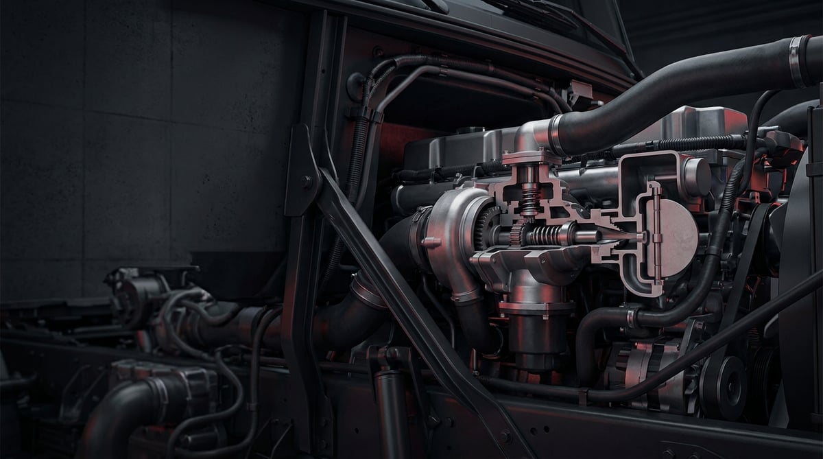
When a heavy commercial vehicle loses engine power, an unfamiliar sooty haze appears at the exhaust outlet and the engine warning lamp stays stubbornly lit, the EGR valve is one of the first three components any technician thinks of. Out in the field this part is usually electrically sound; the real problem is the soot layer built up over the years, which keeps the flap from closing fully or opening fully. This guide explains, through the eyes of a service technician, what the EGR valve and EGR flap actually do, which symptoms point to a fault, the correct diagnostic sequence, the discipline required during removal and refitting, and the maintenance habits that extend service life.
What Is the EGR Valve & EGR Flap? Function and Operating Principle
The EGR valve and EGR flap are controlled flow regulating elements that return part of the exhaust gas to the intake side, lowering combustion temperature and reducing NOx formation; in heavy commercial diesel engines they typically recirculate around 5 to 25 percent of the exhaust gas depending on the operating point, are in constant contact with gas in the 400-700 °C range, and change position within seconds according to the signal from the engine control unit.
The naming gets mixed up in the workshop, so let us separate the two from the start. The EGR valve is the main control element that determines how much exhaust gas is recirculated; it is usually mounted on the exhaust manifold or at the outlet of the EGR cooler. The EGR flap, on the other hand, is the butterfly type element that creates or directs the pressure difference which makes the flow possible: it throttles the intake side to lower intake pressure, or builds back pressure on the exhaust side so the gas can pass into the intake tract. In catalogues these two parts are often listed under the same family, because the causes of their failures and the remedies are largely shared.
The operating principle is thermodynamically simple. In a diesel engine, nitrogen oxide (NOx) formation is directly related to peak in-cylinder temperature; once the temperature rises above a certain threshold, the nitrogen in the air begins to combine with oxygen. Exhaust gas is largely non-combusting, oxygen-depleted gas with a higher specific heat capacity than fresh air. When a controlled portion of this gas is mixed into the intake air, the oxygen density of the charge drops, combustion takes place more slowly and at a lower peak temperature, and NOx formation falls noticeably. In return, the tendency to produce soot (particulates) increases; that is why the EGR rate is precisely limited in the engine map according to load and speed.
In heavy commercial vehicles the recirculated gas is generally not fed straight into the intake. It first passes through an EGR cooler, releasing heat into the engine coolant circuit; this preserves intake air density so volumetric efficiency does not drop. The gas leaving the cooler is directed to the intake manifold or to a mixing (venturi) element in the proportion set by the EGR valve. The engine control unit manages this loop not as an open loop but with feedback: air mass flow, intake manifold pressure, EGR differential pressure and valve position sensor data are compared, and if the actual flow deviates from the target a fault code is generated.
Control types: pneumatic, electric and vacuum operated
Three control architectures are common in heavy commercial applications. In pneumatically controlled valves, pressure taken from the vehicle air system is fed through a proportional solenoid to a diaphragm or piston actuator; this is the most frequent solution in trucks and buses because compressed air is already available on the vehicle. In electrically controlled valves, a DC motor or torque motor turns the shaft through a gear set and an integrated position sensor reports the actual opening to the ECU; response speed and positional accuracy are high. The vacuum operated type is still encountered in the light and medium commercial classes. The environmental durability class of electric actuators is generally assessed in the industry using the road vehicle electrical/environmental conditions approach of the ISO 16750 family; the emission type approval to which the engine is subject falls under ECE R49 in heavy commercial applications. Which class a given part belongs to and which approval it carries must be verified from the relevant OE catalogue.
Components and auxiliary elements
- Valve body and flap/piston assembly: The moving core that restricts or opens the flow.
- Actuator: Electric motor, pneumatic diaphragm or vacuum capsule.
- Position sensor: Potentiometric or contactless sensor reporting the actual opening to the ECU.
- EGR cooler: Heat exchanger transferring the heat of the recirculated gas to the engine coolant.
- Differential pressure (delta-P) sensor and pressure hoses: Used for indirect measurement of the flow rate.
- Flange gaskets and metal gaskets: Single-use sealing elements operating at high temperature.
- Connecting pipes and bellows (compensator): Intermediate elements absorbing thermal expansion and vibration.
- Electrical connector and wiring harness: The auxiliary element most exposed to thermal ageing.
| Control type | Typical application | Supply / signal (general reference) | Characteristic service note |
|---|---|---|---|
| Pneumatic (compressed air) controlled valve | Truck, tractor unit, bus; heavy commercial vehicles with an air system | Vehicle air system typically 8-12.5 bar; proportional solenoid 24 V | Moisture and oil in the air supply line clog the solenoid |
| Electric (DC motor) controlled valve | Euro 5 / Euro 6 generation modern heavy commercial engines | 24 V supply, PWM control, integrated position sensor | Position deviation can also stem from soot, check mechanically first |
| Vacuum operated valve | Light and medium commercial, some older generation applications | Vacuum pump line, solenoid switching | Diaphragm perforation and cracked vacuum hose are common |
| Intake side EGR flap (throttling butterfly) | Generating pressure difference during cold running and at high EGR demand | Electric actuator, position feedback | Will not close fully once soot builds up, idle becomes rough |
| Exhaust side flap (back pressure butterfly) | Installations that build back pressure to push gas into the intake | Pneumatic or electric | Shaft bearing seizure is seen at high temperature |
How do you tell that the EGR valve & EGR flap has failed?
EGR valve and EGR flap failures fall into two main behaviours in the field: the valve staying open more than required, and staying closed more than required. A valve stuck open feeds too much exhaust gas into the intake at high load, producing power loss and black smoke; a valve stuck closed shows itself through increased NOx and an emission related fault code. The table below matches field symptoms with probable causes and verification methods.
| Symptom | Probable cause | Check / verification |
|---|---|---|
| Noticeable power loss at high load, black smoke from the exhaust | Valve held open by soot, flap not closing fully | Comparison of requested and actual valve position in live data; inspection of the flap seating face on the removed valve |
| Rough idle, vibration and misfiring when cold | Soot build-up on the intake side flap, shaft seizure | Monitoring full open-close travel of the flap with an actuator test; endoscopic inspection inside the duct |
| Engine warning lamp together with an "insufficient EGR flow" type fault code | Duct or cooler blocked, valve stuck closed, differential pressure hose filled with soot | Differential pressure sensor live data; removing the hoses and verifying they are clear |
| Engine coolant level dropping, white smoke and a sweetish smell from the exhaust | Internal leak in the EGR cooler, cracked heat exchanger tubes | Pressure test of the cooling circuit; exhaust gas test at the expansion tank; separate pressure test of the cooler |
| Increased fuel consumption and more frequent DPF regeneration | Continuously excessive EGR flow, worn valve seating face | Reading regeneration history and soot load data; monitoring the EGR rate in live data |
| Actuator does not move at all, position feedback stays fixed | Electric actuator motor faulty, connector oxidised, break in the wiring harness | Measuring supply and signal at the connector; actuator resistance measurement; actuator command from the diagnostic tool |
| Pneumatic valve moves slowly or incompletely | Moisture/oil blockage in the solenoid, restriction in the air line, perforated diaphragm | Measuring air supply pressure at the valve inlet; commanding the solenoid directly and watching the movement |
| Soot traces around the manifold or flange area, whistling exhaust noise | Burnt flange gasket, loosened bolts, cracked bellows | Visual tracing of soot marks on a cold engine; checking bolt torques; leak detection with soapy water |
Is reading the fault code enough?
A fault code is the start of the diagnosis, not its conclusion. A code of the "EGR flow below target" type does not say the valve is defective, it says the system cannot achieve the targeted flow. The same code may originate from a blocked cooler, a differential pressure hose filled with soot, a leaking flange gasket, or a genuinely seized valve. The most common mistake in the field is attributing the code directly to the valve and replacing a sound part; the code is cleared and the vehicle comes back a few hundred kilometres later with the same code.
Position verification with live data
On electrically controlled valves the fastest discriminating test is comparing the requested position with the actual position. Using the diagnostic tool, the valve is driven in steps to 0, 25, 50, 75 and 100 percent opening; the feedback value is expected to follow the command without delay and without sticking. Sticking at a particular opening, or feedback never reaching the command, is the classic signature of mechanical resistance caused by soot. Repeating the same test with the engine cold and again after it has warmed up also reveals seizures that appear with thermal expansion.
Separating a cooler related fault
An internal leak in the EGR cooler is easily confused with a valve fault, because both can produce similar codes and a similar smoke picture. The distinguishing sign is the coolant: if the level drops without any visible external leak, bubbles form in the expansion tank while the engine is running, or dense white smoke that does not disperse in cold weather comes from the exhaust, the cooler should be questioned before the valve. For verification the cooler is tested separately by pressurising the system; if this step is skipped, the newly fitted valve is soon covered with soot and residue again.
Standards and further reading
For the regulatory background on this subject, see Regulation (EC) No 595/2009 (Euro VI heavy-duty emissions). Always confirm specific figures and procedures against the current regulation and the vehicle manufacturer service data.
How is the EGR valve & EGR flap replaced? Step by step
EGR valve and EGR flap replacement is, when carried out in the right order, a job of a few hours on most heavy commercial applications; what stretches the job is not the part itself but access and the condition of the bolts being removed. The steps below are a general service flow; for the procedure and torque values specific to the engine code, the vehicle manufacturer's current service manual prevails.
- Secure the vehicle and record the fault memory: Before starting removal, record the existing fault codes, freeze frame data and EGR live values; this record is the comparison baseline for verification after refitting. Then stop the engine, apply the parking brake, chock the wheels, check the tilt safety catch on cab-over vehicles, wait for the engine and exhaust line to cool, and disconnect the battery isolator or the negative terminal.
- Open up access: Remove the engine top cover, heat shield, air filter pipe, cable duct and, if necessary, the turbo intake pipe and any other parts blocking access. Mark and separate every removed part; many of the bolts in the EGR area are of different lengths.
- Disconnect the electrical and pneumatic connections: Release the connector lock gently and pull it out by the body, not by the cable. Mark and disconnect the pneumatic lines; plug the hose ends with clean caps.
- Clean the area: Clear soot, dust and oil from around the flanges to be removed using compressed air and a clean cloth. Immediately cover every exhaust and intake opening you expose; a bolt or piece of gasket dropped into the intake duct means turbo and cylinder damage.
- Loosen the bolts gradually, applying heat: Bolts on the exhaust side may be seized due to thermal cycling. Apply penetrating oil, use controlled heat if necessary, and loosen the bolts in opposite pairs and in stages. Instead of continuing to turn a bolt that is resisting, stop and change the method; a sheared bolt adds hours to the job.
- Remove and inspect the valve and flap: Assess the removed part for flap seating face condition, shaft play, body cracks and soot thickness. The colour and structure of the soot layer are informative: dry, brittle soot indicates normal ageing, while oily, sticky residue may point to a crankcase ventilation or turbo related oil leak.
- Check the ducts and neighbouring elements: Verify that the EGR pipe, mixing element, intake duct and differential pressure hoses are clear. A new valve fitted onto a blocked duct will bring back the same fault code within a short time. If necessary, pressure test the cooler separately.
- Verify the new part: Place the new valve side by side with the old one and compare flange hole spacing, hole angle, body length, connector type and actuator orientation. On valves with a position sensor, the connector pin count and lock type must be identical. Do not force a part that does not fit just because it is "close enough".
- Fit with a new gasket and torque in the correct sequence: Flange gaskets and metal gaskets are single-use and are always replaced with new ones. Seat the bolts by hand first, then tighten them with a torque wrench in opposite (cross) sequence and in the stages specified by the manufacturer. Heat resistant assembly paste is used only if the manufacturer permits it and without smearing it onto the gasket face.
- Complete the connections and carry out the teach-in: Seat the electrical connector until it locks, connect the pneumatic lines according to your markings, and if the cooler was removed, fill and bleed the cooling circuit as per procedure. Many electric valves require an end stop teach-in (adaptation) after fitting; if this step is skipped the position feedback drifts and the fault code returns.
- Test and verify: Clear the fault codes, start the engine, and check the flange area for soot and leaks at idle and at mid speed. Confirm in live data that the requested and actual valve positions match, then carry out a loaded test drive and re-read the codes on return. If the cooler was touched, check the coolant level again after the test drive.
What mistakes are most often made when replacing the EGR valve & EGR flap?
EGR valve and EGR flap replacement errors are mostly related not to the part itself but to neglect of the surrounding system. The warnings below gather the typical situations that bring the same vehicle back into the workshop within a short time.
- Reusing the gasket: A flange gasket that has been through thermal cycling is crushed once; on second use it leaks soot and gas.
- Not checking the differential pressure hoses: A thin hose filled with soot makes a sound valve look guilty.
- Skipping the cooler: A new valve fitted on top of a blocked or leaking cooler soon ends up in the same condition.
- Not performing the adaptation/teach-in: On electric valves the position feedback drifts if the end stops are not taught.
- Tightening bolts in one go without a torque wrench: The flange distorts, the gasket does not seat properly, and leakage starts at the first thermal cycle.
- Leaving the intake duct open: A piece of gasket or a bolt dropped into the duct during removal reaches the turbo and the cylinder.
- Cleaning inside the body with aggressive chemicals: Solvent reaching the actuator, sensor and bearing area damages the electronics and the shaft lubrication.
- Taking no precautions against soot dust: Diesel soot must not be inhaled; cleaning is done with a mask and ventilation.
- Selecting the part by vehicle model alone: Different valves may be used on the same model depending on emission generation; the engine code and OE number are essential.
- Handing the vehicle over without a test drive: Most EGR related codes can only be re-verified under a loaded drive.
EGR valve & EGR flap technical values and check points
EGR valve and EGR flap values given below are general reference ranges frequently encountered in heavy commercial vehicle applications. Engine family, emission generation, cooler type and equipment level shift these ranges; for exact data always consult the current OE service manual matching the vehicle's engine code.
| Parameter | Typical range (general reference) | Note |
|---|---|---|
| Exhaust gas temperature at the valve inlet | 400-700 °C | Varies with load and speed; short-term peak values may be higher |
| EGR cooler outlet gas temperature | Typically 100-250 °C | This value rises noticeably as the cooler becomes blocked |
| EGR rate according to operating point | Approximately 5-25 percent | Usually drops at full load; the map is engine specific |
| Electrical system supply voltage | 24 V nominal (heavy commercial) | Voltage drop during cranking may look like an actuator fault |
| Pneumatic control air pressure | Vehicle system pressure typically 8-12.5 bar | The proportional solenoid output produces control below this pressure |
| Valve position feedback deviation tolerance | Narrow tolerance, engine specific | The acceptance limit is taken from the service manual; verified with live data |
| Cooling circuit pressure test | Generally in the order of 1-2 bar | Used to isolate an internal cooler leak |
| Acceptable soot layer | At a level that does not prevent the flap from seating fully | If there is scoring or a gap on the seating face, the part is renewed |
| Connection point | Typical torque band (general reference) | Application note |
|---|---|---|
| Valve flange bolt (M8 class) | 20-30 Nm | Tightened in cross sequence, in stages; a new gasket is mandatory |
| Cooler and pipe flange (M10 class) | 35-50 Nm | Bolts may be seized due to thermal expansion |
| Actuator mounting bolt | 8-12 Nm | Overtightening distorts the body and seizes the shaft |
| Sensor and differential pressure connection | 8-15 Nm | The sensor body is usually plastic; tighten with a torque wrench |
| Clamp and bellows connections | 6-12 Nm | The compensator is secured in a free position, without being strained |
- Does the valve position feedback follow the requested value without delay, is there any sticking in the stepped test?
- Are there soot traces, soot blow-by or a whistling noise in the flange area?
- Is the coolant level stable, are bubbles forming in the expansion tank?
- Are the differential pressure hoses clear, is there a soot plug at their ends?
- Is the electrical connector free of oxidation and fully locked, is the harness chafing against the exhaust?
- Is there moisture, oil or cracking in the pneumatic lines?
- Have the air filter, turbo and crankcase ventilation been ruled out as soot sources?
- Are the DPF soot load and regeneration frequency within the normal band?
How is the EGR valve & EGR flap maintained and its service life extended?
EGR valve and EGR flap service life is generally not defined by a fixed "replacement interval" by manufacturers; what determines life is the duty profile, fuel and oil quality, and the overall soot production of the engine. In long haul duty where the engine regularly reaches operating temperature the valve can work faultlessly for many years, whereas in short distance, low load urban duty with frequent idling, soot build-up accelerates markedly. The most common picture in the field is a technically sound valve that can no longer do its job purely because of soot.
- Periodic oil and filter service: The manufacturer's interval must be observed and the engine oil chosen to the specification appropriate for the vehicle's emission generation. Oil derived residue makes soot sticky and locks the flap.
- Air filter discipline: Restricted air intake leads to incomplete combustion and therefore to more soot.
- Fuel quality: Fuel from an unknown source degrades both injection quality and soot structure.
- Crankcase ventilation and turbo sealing: Oil vapour carried into the intake is the main accelerator of build-up in the EGR area; it should be checked at every service.
- Bringing the engine up to operating temperature: Constant short distances and long idling reduce the system's self-cleaning capability. Regular loaded driving should be carried out whenever possible.
- Not postponing a fault code: Acting when the first EGR related warning code appears prevents an expensive repair that later spreads to the cooler and the DPF.
- Periodic visual inspection: Flanges, bellows, electrical connector, pneumatic lines and heat shield should be reviewed at every service.
- Health of the cooling system: The correct antifreeze mixture and a clean circuit delay internal corrosion of the EGR cooler.
In fleet operations the most efficient approach is to plan the EGR valve not as a single part but as a group. Handling the flange gaskets, the differential pressure hoses and, if necessary, the cooler during the same service visit as the valve replacement is far more economical than the cost of taking the vehicle off the road a second time a few months later. A loaded test drive before the vehicle goes back into service, followed by a repeat code reading on return, is the cheapest insurance against a roadside breakdown.
Related categories: Egr Valve · Egr Throttle
Related technical guides: Exhaust Manifold: Cracks, Leaks, Replacement & Torque Guide · Engine Cylinder Head Group: Faults, Replacement & Maintenance · Exhaust / Engine Brake: Faults, Replacement & Maintenance Guide · Oil Cooler: Failure Symptoms, Replacement & Maintenance Guide · Truck Oil Pan Group: Faults, Replacement & Maintenance Guide
Application and compatibility: Vehicle compatibility catalogue · Engine compatibility catalogue
Main guide: What Is an EGR Valve? Failure Symptoms and Cleaning (Heavy Commercial Vehicles)
Tags
Frequently Asked Questions
- What does an EGR valve do?
- The EGR valve returns part of the exhaust gas to the intake side in a controlled manner. The returned gas lowers the oxygen density of the charge, combustion takes place at a lower peak temperature and nitrogen oxide (NOx) formation is reduced. In heavy commercial diesel engines this function is an inseparable part of the vehicle's emission type approval, and correct valve operation is necessary both for emission compliance and for engine performance.
- What symptoms does an EGR valve fault produce?
- The most common symptoms are power loss at high load, black smoke from the exhaust, rough idle, the engine warning lamp coming on, increased fuel consumption and the particulate filter regenerating more often than normal. If the valve stays open, power loss and smoke dominate; if it stays closed, an emission related fault code comes to the fore. If the EGR cooler is also involved, coolant loss and white smoke appear as an additional symptom.
- Can an EGR valve be cleaned, or does it always have to be replaced?
- If the soot build-up has not yet damaged the seating face, the valve can be brought back into service with a suitable cleaner and mechanical cleaning. However, if the flap seating face is worn, there is play in the shaft bearing, the body is cracked or the actuator has an electrical fault, cleaning will not provide a lasting remedy and the part must be renewed. During cleaning it is critical that solvent does not reach the actuator and sensor area.
- What is the difference between an EGR valve and an EGR flap?
- The EGR valve is the main control element that directly determines the amount of exhaust gas recirculated, and it is usually mounted on the exhaust manifold or at the cooler outlet. The EGR flap is the butterfly type element that produces the pressure difference required for the flow to occur; it throttles the intake side to lower intake pressure, or builds back pressure on the exhaust side. The two work together: the flap prepares the pressure difference and the valve meters the quantity.
- Can you keep driving with a faulty EGR valve?
- It is not recommended. Continuing to drive with a faulty EGR valve can cause the engine to enter power limitation, increase soot load and clog the particulate filter prematurely. In addition, emission values fall outside the type approval and become grounds for failure at vehicle inspection. When the warning lamp comes on, going to a workshop as soon as possible is both cheaper and safer.
- Why does an EGR valve keep sooting up?
- Soot build-up generally originates not from the valve itself but from the engine's soot production and from oil vapour carried into the intake. A blocked air filter, a turbo or crankcase ventilation leaking oil, low quality fuel, incomplete combustion and short distance duty where the engine never reaches operating temperature are the most frequent causes. Eliminating these root causes before fitting a new valve prevents a repeat of the same fault.
- How long does EGR valve replacement take?
- What determines the time is not the part itself but access. On a valve reached by removing the top cover, the job takes a few hours in most applications including cleaning and verification. On installations requiring cab tilting, heat shield and intake pipe removal, or where the cooler is renewed as well, the job can extend to half a day, and to a full day on engines with difficult access. The adaptation procedure and a loaded test drive must be added to this.
- Why does the fault code come back after EGR valve replacement?
- There are three most frequent reasons: the end stop teach-in (adaptation) not being carried out after fitting, the actual restriction in the system not having been removed (blocked cooler, soot filled duct or differential pressure hose), and a leaking flange gasket. Before the code is cleared, it should be confirmed in live data that the requested and actual valve positions match, and the result should then be verified with a loaded test drive.
- How do I choose the right EGR valve?
- The vehicle model alone is not enough. The engine code, year of manufacture, emission generation (Euro 5 / Euro 6), control type (pneumatic or electric), connector pin count and, where possible, the OE reference number on the removed part should be used together. In the VADEN catalogue the search can be made both by engine code and by OE reference number; placing the new part side by side with the old one before fitting and comparing flange hole spacing, body length and connector type is the safest final step.
- Can an EGR cooler fault be confused with a valve fault?
- Yes, frequently. A blocked EGR cooler causes the targeted flow not to be achieved and an "insufficient EGR flow" type code to be generated even when the valve is sound. A cooler with an internal leak, on the other hand, produces coolant loss and white smoke. To tell them apart, the cooling circuit should be pressure tested, the expansion tank checked for gas bubbles, and the cooler tested separately where possible.
Related Articles

Oil Filter Cap and Housing: Leaks, Cracks and Seal Replacement
Truck engine oil filter cap and housing: why plastic caps crack, O-ring leak causes, bypass valve faults, and correct torque and seal replacement steps.
Piston Rings: Oil Consumption, Compression Loss and Replacement
Ring-related oil consumption and compression loss in truck diesel engines: how rings seal, blow-by and leak-down tests, ring gap and replacement.
Intake Manifold and Intake Pipe: Faults, Diagnosis, Repair
How the intake manifold and charge air pipe work on truck diesel engines, how to spot boost leaks, run a pressure test and fit them leak free.


