Clutch Release Bearing: Fault, Replacement and Care Guide
How a truck clutch release bearing works, how to spot noise and pedal symptoms, measure release travel, replace it correctly and extend its life.
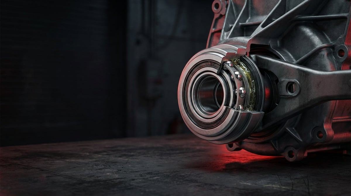
When a heavy commercial vehicle produces a high-pitched whirring noise the moment the clutch pedal is pressed, a hum that disappears as soon as the pedal is released, or a fine vibration felt through the foot, the first part most technicians think of is the clutch release bearing. Everyday workshop experience supports that instinct: the source of the noise is usually not the disc or the pressure plate, but the bearing that sits between them and carries the entire release force. This guide explains, from a service point of view, what the clutch release bearing does, which symptoms indicate that it is failing, the correct diagnostic sequence, the discipline required during removal and refitting, and why it should never be replaced on its own.
What Is a Clutch Release Bearing? Function and Operating Principle
The clutch release bearing is a ball bearing element that, when the clutch pedal is pressed, applies axial force to the diaphragm springs of the pressure plate assembly to break the friction link between the flywheel and the friction lining, carrying the movement between the rotating pressure plate and the stationary release fork. In heavy commercial applications, typical release travel is in the 10-16 mm band, while release force is in the order of 1,000-3,500 N.
The part goes by several names in the field and in catalogues: clutch release bearing, clutch bearing, throw-out bearing, release bearing, and in German OE documentation Ausrücklager. All of them describe the same function; regardless of the name used in the search, the selection criteria do not change: chassis and engine code, clutch diameter and OE reference number.
The operating principle is a force chain. When the driver presses the pedal, the movement is transmitted to the bearing through a cable or rod and the release fork in mechanical systems, and through the master cylinder and the slave cylinder in hydraulic systems. The bearing slides forward along the guide sleeve fitted over the clutch shaft and contacts the rotating diaphragm spring fingers. This is the critical point: the surface it touches rotates at engine speed, while the fork applying the force is stationary. What separates these two worlds is the bearing itself. The ball row between the inner and outer race isolates the rotational movement while carrying the axial thrust force without difficulty.
The clutch is the area of the vehicle that sees the highest instantaneous thermal and mechanical load, and the bearing sits right inside that load. On a heavy commercial vehicle, the clutch release bearing is loaded at full engine speed for a matter of seconds every time the pedal is pressed, then unloaded again. The load-unload cycle is the real factor determining bearing life; for that reason, the bearing life of an urban distribution truck and a long-haul tractor unit differ greatly when expressed in kilometres.
Which standard is bearing life calculated against?
The clutch release bearing is, ultimately, an axially loaded ball bearing, and its theoretical life is assessed using the approach found in general bearing literature, that is the ISO 281 basic rating life (L10) logic: the operating period that 90 percent of bearings are expected to reach under a given load and speed. On the static load capacity side, ISO 76 is used as a reference, and for race and ball geometry the ISO/DIN bearing dimension standards (axially loaded ball bearing families) apply. In practice this calculation alone does not explain field life, because the clutch release bearing is loaded intermittently rather than continuously, and its real life is determined by the duty profile and thermal conditions. The exact life expectancy for a given application, along with geometry and load class, must be verified from the relevant OE catalogue.
The difference between a concentric (hydraulic) bearing and a conventional bearing
Two different architectures live side by side on modern heavy commercial vehicles. In the conventional layout, the bearing sits on a carrier that slides along the guide sleeve and is pushed by the release fork; the hydraulic cylinder generating the release force is external and bolted to the gearbox housing. In a concentric release system, the hydraulic cylinder and the bearing are combined in a single body; this ring-shaped unit, mounted on the gearbox front cover, moves directly around the clutch shaft and eliminates intermediate elements such as the fork, the guide sleeve and the adjustment mechanism. The concentric type has two defining service characteristics: because the release clearance is compensated automatically, there is no separate pedal free play adjustment, and in the event of a failure the bearing and the cylinder are replaced together as a complete unit.
Which release architecture is common across heavy commercial vehicle families?
Clutch diameter and release architecture are determined by the engine and gearbox combination rather than by the make name; even so, general tendencies can be described family by family. On latest-generation long-haul tractor units such as the Mercedes-Benz Actros, MAN TGX, Volvo FH and DAF XF, single-plate clutches in the 430 mm class combined with concentric hydraulic release units mounted on the gearbox front cover have become widespread; these vehicles have no separate release fork or guide sleeve, and the unit is replaced complete. On the Scania R series, on older Actros and TGA generations and on distribution class vehicles, clutches in the 362-395 mm class and the conventional push-type architecture working with an external cylinder and release fork are still widely encountered; pull-type solutions are largely specific to certain pressure plate families. Because different engine generations and gearbox codes under the same model name use different units, select the part not by make or model but by engine and chassis code and OE reference number.
Components and ancillary elements
- Bearing body (inner and outer race and ball row): the main element carrying the axial force.
- Contact face: the hardened race face that seats against the diaphragm spring fingers.
- Carrier sleeve / guide sleeve: the seat that allows the bearing to slide along the clutch shaft axis.
- Release fork and pivot point: the lever that transfers force to the bearing in the conventional system.
- Concentric release unit (hydraulic bearing): the assembly combining cylinder, piston, seal and bearing in a single body.
- Spring clip, retainer and circlip: the small but critical parts keeping the bearing on the fork.
- Permanent grease fill and seal: the bearing's lifetime lubrication; external greasing is not foreseen.
| Bearing type | Source of release force | Typical travel / free play | Characteristic service note |
|---|---|---|---|
| Conventional push type bearing | Release fork, external hydraulic cylinder or mechanical linkage | Release travel 10-16 mm, pedal free play 15-30 mm | Fork and guide sleeve wear are checked separately |
| Pull type bearing | Fork releases the diaphragm by pulling rather than pushing | Similar release travel, fitting direction critical | Bearing locks onto the pressure plate; removal requires a special procedure |
| Concentric hydraulic release unit | Ring piston integrated into the housing | Automatic clearance compensation, no separate pedal free play | Bearing and cylinder are replaced as a complete unit |
| Semi-concentric type with cylinder bolted to the gearbox cover | Cylinder bolted to the cover plus a short fork | Free travel depends on the manufacturer's definition | Cylinder seal and bearing are assessed separately |
| Bearing working with a self-adjusting pressure plate | Compensation mechanism inside the pressure plate | Pedal effort stays more constant throughout service life | Pressure plate and bearing are treated together, as a set |
How is a clutch release bearing failure identified?
A clutch release bearing failure almost always announces itself through noise and pedal feel; it rarely dies quietly. The golden rule of diagnosis is to determine whether the noise is heard with the pedal pressed or with the pedal released. This single observation largely separates a bearing fault from a gearbox input shaft bearing fault. The table below matches field symptoms with likely causes and measurable verification methods.
| Symptom | Likely cause | Check / verification (with measurement) |
|---|---|---|
| High-pitched whirring or hum that starts when the pedal is pressed and stops when it is released | Wear in the bearing ball row, grease loss, seal damage | Engine at idle, gearbox in neutral: if the noise starts within the first 20-30 mm of pedal travel, suspicion points directly at the bearing |
| Noise heard with the pedal released that decreases when it is pressed | Gearbox input shaft bearing or pilot bearing (not the release bearing) | The same test is read in reverse; if the noise stops when the pedal is pressed 20-30 mm, the culprit is on the input side |
| Vibration in the pedal, a throbbing felt through the foot | Uneven wear on the bearing face, diaphragm fingers not level with one another | After the cab is tilted, the finger tips are scanned with a dial indicator; the plane deviation between tips should not exceed the order of 0.1 mm |
| Gears will not engage or engage only with force, difficulty pulling away | Insufficient release distance; loss of travel, air in the hydraulics, worn fork | Diaphragm finger tip movement is measured; a value below the 10-16 mm band indicates loss of travel |
| Pedal has become stiff, more effort than normal is needed to release the clutch | Bearing binding on its slides, guide sleeve worn or dry | Pedal free play is measured (15-30 mm in a conventional system); after removal, free sliding of the carrier is checked |
| Pedal has gone soft, does not hold at the floor, release is delayed | Internal seal leakage in the concentric release unit or air in the circuit | The pedal is held at the floor for 30 seconds; the pedal slowly sinking indicates internal leakage |
| Hydraulic fluid trace or drips around the bell housing | Concentric bearing seal or connecting line is leaking | The area is cleaned and the pedal pressed 10-15 times to trace the direction of wetting; the reservoir level is marked and compared |
| Removed bearing binds, has play or feels metallic when turned by hand | Internal bearing damage, pitting in the ball row | The removed part is turned 2-3 revolutions by hand; axial and radial play is checked by hand and any perceptible play is unacceptable |
| Bright, hollowed or asymmetric wear mark on the bearing face | Bearing has run off-axis, fork or guide sleeve worn | The face mark is compared with the diaphragm finger marks; a mark deepening on one side indicates axial misalignment |
The pedal test: reading where the noise occurs
The fastest and cheapest diagnostic method is to press and release the pedal slowly with the engine at idle and the gearbox in neutral. If the noise increases as the pedal is pressed and disappears when it is released, the clutch release bearing is the prime suspect, because the bearing is only loaded and rotating while in contact. If the noise is present with the pedal released and decreases when it is pressed, suspicion shifts to the gearbox input shaft bearing. Repeat the test several times and hold the pedal down for a few seconds to listen for any change in the character of the noise. This distinction also prevents the most frequent unnecessary gearbox removal seen in the field.
Measuring the release distance
Behind a complaint of poor gear engagement there is usually insufficient release distance. The check is made by measuring the axial movement obtained at the tip of the diaphragm spring fingers with the pedal fully pressed; the measurement is taken with a dial indicator or a suitable gauge through the bell housing cover or inspection plug. If the measured value is below the minimum release distance defined by the manufacturer, the problem lies in one of three places: air or internal leakage in the hydraulic circuit, a worn fork or pivot, or a bearing of the wrong height. Replacing parts without taking a measurement usually brings the complaint straight back.
Hydraulic circuit and seal check
On vehicles using a concentric release unit, the first sign of a bearing fault is not noise but pedal feel. If the pedal has gone soft, does not hold at the floor or the release happens with a delay, there is air in the circuit or internal leakage inside the unit. To confirm, the hydraulic reservoir level is monitored, the lower drain opening of the bell housing is checked for wetness, and the pedal is held down for 30 seconds to observe any sinking. Clear hydraulic fluid dripping from the bell housing is the clearest finding requiring complete replacement of the concentric bearing; on this type of unit the seal is not renewed on its own.
Further reading
For a plain-language technical overview of this subject, see the reference article on Wikipedia. Always confirm specific figures and procedures against the vehicle manufacturer service data.
How is a clutch release bearing replaced? Step by step
Clutch release bearing replacement requires planned and disciplined work, because the gearbox has to be removed from the vehicle; on a heavy commercial vehicle, the weight of the gearbox and the cab tilting operation are the two most hazardous steps of the job.
- Make the vehicle safe: Park on level ground, apply the parking brake, fit chocks, bleed the air pressure and disconnect the negative battery terminal. On tilting cab vehicles, raise the cab and lock the safety catch.
- Record the complaint: Before removal, measure and note the pedal free play, the pedal effort and, where available, the release distance. These values will be the reference for checking correct adjustment after reassembly.
- Disconnect the hydraulics and connections: Remove the slave cylinder line, the gear control linkages, the speed sensor and switch connectors and, where fitted, the output shaft flange. Cap open hydraulic ends immediately; hydraulic fluid damages paintwork.
- Support and lower the gearbox: Take the weight of the gearbox on the jack and secure it with a strap, loosen the bell housing bolts in a crosswise sequence and draw the gearbox back parallel to the clutch shaft axis. The unit must never be left hanging on the input shaft under its own weight; if the shaft bends, the disc hub and the bearing are damaged at the same time.
- Remove the bearing and inspect the removed parts: Take out the spring clip or circlip and separate the bearing from the fork; on pull type units the bearing is locked to the pressure plate, so the special removal sequence defined by the manufacturer must be followed, as forcing it permanently damages the pressure plate diaphragm. Turn the removed bearing by hand and check for binding and play; record the wear mark on the face, any hollowing of the diaphragm finger tips, the lining thickness, the flywheel surface and any oil traces in the bell housing. The findings reveal the root cause of the failure; simply replacing the part is not enough.
- Check the guide sleeve and the fork: Look for grooves, scoring or ovality on the guide sleeve surface where the bearing slides, and for wear on the fork tips and pivot point. A worn guide sleeve or fork will destroy the new bearing in exactly the same way; these parts must be renewed in the same service visit if required.
- Renew the clutch set together: The friction disc, the pressure plate and the bearing share the same thermal and mechanical history. While the gearbox is out, replace all three as a set; check the flywheel surface and have it machined or renewed if necessary. Also assess the flywheel run-out and the rear crankshaft seal at this stage.
- Fit the new bearing correctly: Place the new bearing next to the old part and compare the outside diameter, the inside diameter, the overall height and the face form. Apply a thin film of the high temperature grease specified by the manufacturer to the guide sleeve; never pack grease into the bearing itself, as it is permanently lubricated. Confirm by hand that the clip is fully seated.
- Refit the gearbox in alignment: Centre the disc with an alignment mandrel and bring the gearbox into place moving it straight and on axis. Tighten the bell housing bolts in a crosswise sequence to the torque specified by the manufacturer. Never attempt to pull the gearbox into place with the bolts at any stage.
- Fill and bleed the hydraulics: Connect the line, fill the reservoir with fluid to the correct specification and bleed it according to the procedure. On vehicles with a concentric release unit, the bleeding sequence is manufacturer-specific and, if skipped, the pedal will not hold at the floor.
- Complete adjustment and testing: Check the pedal free play and the release distance against the manufacturer's values (there is no free play adjustment on concentric systems). Start the engine and try the gear changes, check the bell housing area with a dry cloth, carry out a short test drive and, on return, reassess both the noise and the sealing.
What are the most common mistakes in clutch release bearing replacement?
Most of the mistakes made during clutch release bearing replacement stem not from the part itself but from a lack of discipline around the job; the most frequent situation seen in service practice is replacing only the bearing while the gearbox is out and having the vehicle come back for the same job a short time later.
- Replacing the part without investigating the root cause: A bearing renewed without finding a worn fork, a dry guide sleeve or a leaking rear crankshaft seal will fail again the same way.
- Closing up without measuring the release distance: A complaint of gears not engaging usually comes not from the part but from insufficient travel; assembly without measurement leaves the job half done.
- Leaving the gearbox hanging on the input shaft: The weight of the unit is carried through the shaft onto the disc; the disc hub and the new bearing are damaged on the very first day.
- Attempting to join up without centring the disc: Without a mandrel the shaft is forced and the lining hub is crushed during assembly.
- Pulling the gearbox in with the bell housing bolts: The bell housing face and dowels are stressed, and an off-axis joint loads the bearing asymmetrically.
- Skipping the removal procedure on pull type units: The bearing is locked to the pressure plate; pulling it by force permanently damages the diaphragm fingers.
- Trying to replace only the seal on a concentric bearing: The concentric unit is a complete part; a leaking body requires replacement, not repair.
- Incomplete bleeding of the hydraulics: The pedal will not hold at the floor, release remains insufficient and the diagnosis unfairly blames the new part.
- Blowing lining dust out with compressed air: This is both wrong from a health point of view and a practice that carries the dust onto the new part.
- Driving with the pedal held at the release point: Even with faultless assembly, this habit is the single fastest way to finish off a new bearing.
Clutch release bearing technical values and inspection points
Clutch release bearing technical values vary significantly with clutch diameter, pressure plate type and release architecture. The ranges below are general references frequently encountered in heavy commercial vehicle applications; they are not binding for any specific chassis or engine code.
| Parameter | Typical range (general reference) | Note |
|---|---|---|
| Heavy commercial clutch disc diameter classes | 310 · 362 · 380 · 395 · 430 mm | Bearing size depends directly on this class |
| Release travel (at the diaphragm finger tip) | 10-16 mm | Below the lower limit, gear engagement becomes difficult |
| Pedal free play (conventional system) | 15-30 mm | There is no adjustment on concentric hydraulic systems |
| Release force (through the bearing) | 1,000-3,500 N | Varies with pressure plate diameter and spring characteristics; approaches the upper band on 430 mm class and pull type pressure plates |
| Plane deviation between diaphragm finger tips | Limits generally in the order of 0.1 mm | Scanned with a dial indicator; if exceeded, the pressure plate is renewed |
| Remaining thickness on riveted lining (replacement threshold) | Replace when roughly 0.3-0.5 mm remains above the rivet head | The exact limit is taken from the service manual |
| Operating temperature inside the bell housing | 80-150 °C, higher during heavy pull-aways | This is why high temperature grease is mandatory |
| Flywheel surface run-out | Limits generally in the order of 0.1 mm | Measured with a dial indicator; manufacturer-specific |
| Expected service life (depending on duty profile) | Roughly 300,000-600,000 km in long-haul use, markedly shorter in urban use | The determining factor is the number of pedal cycles, not the mileage |
| Connection point | Typical torque band (general reference) | Application note |
|---|---|---|
| Pressure plate assembly to flywheel bolts | 40-70 Nm in the M10/M12 class common in heavy commercial use | Tightened crosswise and in stages; the exact value is taken from the OE manual according to bolt diameter and grade |
| Gearbox bell housing bolts | 80-140 Nm in the M12/M14 class common in heavy commercial use | Varies with diameter and strength grade; a crosswise sequence is mandatory |
| Concentric release unit retaining bolts | 10-25 Nm on small diameter (M6/M8) connections | Overtightening cracks the aluminium housing |
| Hydraulic line union / banjo bolt | 25-40 Nm | A new sealing washer at every removal; the value depends on the union size |
| Flywheel to crankshaft bolts | Manufacturer-specific, mostly angle-tightened | Usually single use; no general band applies, always take the value from the manual |
- Does the removed bearing bind, show play or feel metallic when turned by hand?
- Is there asymmetric polishing, hollowing or a deep mark on the bearing face?
- Are the diaphragm spring finger tips on the same plane, and is there hollowing at the tips?
- Is the guide sleeve surface smooth, or has grooving or ovality developed?
- Is there wear at the release fork pivot point and at its tips?
- Are there traces of engine oil or hydraulic fluid inside the bell housing?
- Are the pedal free play and the release distance within the range given by the manufacturer?
- Does the hydraulic reservoir level stay constant, and does the pedal hold at the floor?
How is a clutch release bearing maintained and its life extended?
Clutch release bearing maintenance is not a periodic operation in the classic sense; the part is permanently lubricated and is not greased from outside. What determines its life is not maintenance but driving habits and correct fitting. This is where the clearest difference is observed in service practice: of two vehicles running the same route with the same load, the one whose driver uses the pedal as a footrest has a noticeably shorter bearing life. The bearing is loaded and rotates only when the pedal is pressed; a foot resting on the pedal means running the part under full load all day long.
- Keep the foot off the pedal: A foot resting on the pedal while driving keeps the bearing permanently in contact and under load. This is the single biggest factor affecting service life.
- Select neutral in traffic: During long waits, selecting neutral and taking the foot off instead of holding the pedal down relieves the bearing of unnecessary load.
- Limit pulling away with a slipping clutch: Holding on a gradient by slipping the lining heats both the lining and the bearing; pulling away using the parking brake is the correct technique.
- Keep pedal free play under control: On conventional systems, loss of free play means the bearing runs permanently against the diaphragm; it should be measured at periodic servicing.
- Renew the hydraulic fluid at the interval specified by the manufacturer: Old, moisture-absorbing fluid causes corrosion on the internal surfaces of the cylinder and the concentric unit.
- Deal with leaks immediately: Oil from the rear crankshaft seal or the gearbox input seal makes the lining slip and raises temperatures, finishing off the bearing as well.
- Manage load and gearbox use correctly: On a vehicle labouring in too low a gear with an excessive load, the number of clutch cycles rises; bearing life is consumed by cycles, not by kilometres.
- Keep service records: If the replacement mileage, the part number used and the measured values are recorded, the root cause of the next failure is found far more quickly.
In fleet operations, the most efficient approach is to plan the clutch release bearing not as a single part but as a member of the clutch group. On every job where the gearbox comes out, renewing the friction disc, the pressure plate and the bearing together, checking the guide sleeve and the fork and assessing the flywheel surface is far more economical than the cost of bringing the vehicle back into the workshop a few months later. What determines downtime is not the price of the part but how many times the vehicle has to be lifted.
VADEN ORIGINAL is a manufacturer producing OE quality spare parts for heavy commercial vehicle braking and driveline systems. Our clutch release bearing product family is held in stock in the catalogue with OE references for truck, bus and tractor unit applications; the same release group also covers release forks and fork repair kits, release rings, slave cylinders and clutch servo and master cylinder references. You can search for the part suited to your vehicle by chassis or engine code or by OE reference number, verify it against the compatibility data in the catalogue and order in a way that preserves the integrity of the clutch set.
Related categories: Release Bearing · Release Fork With Bearing
Related technical guides: Clutch Central Unit (Lower/Upper Servo): Faults & Replacement · Clutch Fork: Fault, Replacement and Maintenance Guide · Clutch Hose Failure, Replacement and Maintenance Guide · Hydraulic Clutch Pedal Unit: Fault Diagnosis, Replacement, Maintenance
Application and compatibility: Vehicle compatibility catalogue · Engine compatibility catalogue
Main guide: Clutch Master and Slave Cylinder Failure Symptoms
Tags
Frequently Asked Questions
- How is clutch release bearing noise identified?
- Clutch release bearing noise is a high-pitched whirring or hum that starts when the pedal is pressed with the engine at idle and the gearbox in neutral, and stops when the pedal is released. The noise generally appears within the first 20-30 mm of pedal travel. If the noise is heard with the pedal released and decreases when it is pressed, the source is most probably the gearbox input shaft bearing. This single test largely separates the two faults from one another and prevents unnecessary gearbox removal.
- Can the clutch release bearing be replaced on its own?
- It is technically possible but not recommended. Because the friction disc, the pressure plate and the bearing share the same cycles and the same heat, when one is finished the others are also close to the end of their life. Renewing all three as a set while the gearbox is already out saves the labour of a second removal a few months later and a second period of downtime. During the same job, the guide sleeve, the release fork and the flywheel surface should also be checked.
- What is a concentric (hydraulic) clutch release bearing and how does it differ from a conventional one?
- A concentric clutch release bearing is a ring-shaped unit that combines the slave cylinder and the bearing in a single body and is mounted on the gearbox front cover. In the conventional system, force is transmitted from an external cylinder through the release fork to the bearing, whereas in the concentric type the piston pushes the bearing directly. There are two practical consequences: because the release clearance is compensated automatically there is no separate pedal free play adjustment, and in the event of a failure the bearing and the cylinder are replaced together as a complete unit; on a leaking body the seal is not renewed on its own.
- Which vehicles use a concentric bearing and which use a conventional one?
- Concentric hydraulic release units have become widespread on latest-generation long-haul tractor units such as the Mercedes-Benz Actros, MAN TGX, Volvo FH and DAF XF, and generally on single-plate clutches in the 430 mm class. On the Scania R series, on older Actros and TGA generations and on distribution class vehicles, clutches in the 362-395 mm class and the conventional push type architecture working with an external cylinder and release fork are still widely used. Because different engine and gearbox codes under the same model name carry different units, the selection must be made not by make and model but by engine and chassis code and OE reference number.
- Can the vehicle be driven with a faulty clutch release bearing?
- It can be driven over short distances but this should not be continued. A worn bearing may break up over time, hollow out the diaphragm spring fingers and cause a complete loss of release distance, leaving the vehicle unable to change gear. At that point the job turns from a single bearing replacement into a more expensive repair covering the pressure plate and the friction disc as well. Once the noise is heard, bringing the vehicle in for planned service is the most economical course of action.
- At how many kilometres is a clutch release bearing replaced?
- The clutch release bearing has no fixed replacement interval; its life is consumed by the number of pedal cycles rather than by mileage. On long-haul tractor units replacement is typically seen in the 300,000-600,000 km band, while on frequently stopping urban distribution vehicles this figure drops markedly. The habit of resting a foot on the pedal alone shortens the life considerably. The final replacement decision should be based not on mileage but on noise, pedal feel and measurement of the release distance.
- There is vibration when the pedal is pressed; is the bearing the cause?
- Throbbing felt in the pedal frequently arises from uneven wear on the face of the clutch release bearing or from the diaphragm spring fingers not lying on the same plane. When the bearing runs off-axis, the force varying with every revolution is reflected in the pedal as vibration. The same symptom can also be produced by a worn release fork, an ovalised guide sleeve or flywheel run-out; for that reason all four components should be assessed together once the bell housing is opened.
- Should the clutch release bearing be greased?
- No. The clutch release bearing is filled with permanent grease and sealed; packing grease into it, dipping it in cleaning fluid or spinning it with compressed air damages the part directly. The only surface requiring lubrication is the guide sleeve on which the bearing slides, and there the high temperature grease specified by the manufacturer is applied as a thin film. Excess grease is carried onto the lining inside the bell housing and causes slipping.
- What is release distance and why does it matter?
- Release distance is the axial movement obtained at the tip of the diaphragm spring fingers when the pedal is fully pressed, and in heavy commercial applications it is typically in the 10-16 mm band. When this distance is insufficient, the disc does not separate fully from the flywheel; gears engage with difficulty, noise occurs during shifts and the lining heats up through constant friction. Replacing parts without taking a measurement usually brings the complaint back. The exact value is defined in the vehicle manufacturer's service manual.
- How do I select the correct clutch release bearing?
- The vehicle model alone is not enough for selection. The chassis or engine code, the clutch disc diameter (for example the 362 mm or 430 mm class), the release type (push, pull or concentric hydraulic) and, where possible, the OE reference number on the old part must be used together. For dimensional verification, the outside diameter, inside diameter and overall height of the bearing should be measured with a caliper and compared with the new part. Searching the VADEN catalogue can be done both by application and by OE number.
- I fitted a new bearing but the noise continues; what could be the cause?
- The most common cause is that the root cause has not been eliminated: a worn release fork, an ovalised guide sleeve or a flywheel with run-out loads the new bearing asymmetrically from day one. The second possibility is that the noise was not coming from the bearing at all; sounds originating from the gearbox input shaft bearing, the pilot bearing or a dual mass flywheel have a similar character. The third possibility is assembly related: an off-axis joint or a part of the wrong height disturbs the release distance and keeps the noise going.
Related Articles

Hydraulic Clutch Pedal Unit: Fault Diagnosis, Replacement, Maintenance
How to diagnose a faulty hydraulic clutch pedal unit on trucks, replace and properly bleed it, and maintain it to prevent a spongy clutch pedal.
Clutch Hose Failure, Replacement and Maintenance Guide | VADEN
Clutch hose symptoms, swelling test, step-by-step replacement, torque values and maintenance tips for heavy commercial vehicles — VADEN technical guide.
Clutch Fork: Fault, Replacement and Maintenance Guide
In a heavy truck a sinking or rattling clutch pedal usually starts at the release fork pivot ball, not the pressure plate: diagnosis and replacement.


