Transmission Shift Tower: Faults, Replacement & Maintenance
Transmission shift tower faults, diagnosis, replacement steps, torque and pressure values, maintenance and FAQ for heavy commercial vehicles — VADEN guide.
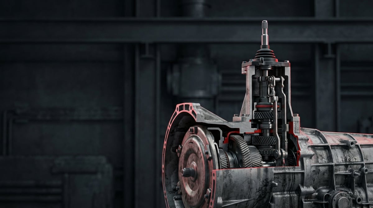
One of the sentences we hear most often in the field is this: "The gearbox is fine, but it won't hold a gear." Most of the time the problem is not in the gears, but at the most critical interface between the driver's hand and the gearbox — the transmission shift tower, commonly known as the gear shift tower. On heavy commercial vehicles the tower mechanically transfers the select and shift movement to the fork shafts inside the gearbox, and on most modern boxes it also carries the range and splitter valves that operate on compressed air. When the tower is worn out the vehicle does not lose traction; the driver simply cannot find the gear. A lever that slips into neutral on pull-away, a 5-6 shift that will not engage on a gradient, or a range valve that locks up at low air pressure are faults that get written up as "gearbox overhaul" in many fleets, when in reality they are a few hours of work on the tower. This guide brings together field-collected practical notes for understanding the tower, diagnosing it correctly, avoiding adjustment errors during removal and refitting, and extending its service life.
What Is a Transmission Shift Tower (Gear Shift Tower)? Function and Operating Principle
The transmission shift tower (gear shift tower) is a mechanical-pneumatic unit bolted to the top cover of the gearbox that transfers the select and shift movement coming from the gear lever or the control cables to the gear fork shafts inside the transmission, and in most heavy commercial applications also carries the pneumatic control together with the range and splitter valves.
Its operating principle is based on a two-axis movement. When the driver moves the lever left and right, the finger (selector shaft) inside the tower rotates and selects which fork shaft it will engage; when the lever is pushed forward or back, the same shaft slides axially, lifts the selected fork shaft out of its detent and presses it onto the synchroniser. To prevent these two movements from interfering with each other, the tower body contains interlock pins and a spring-loaded self-centring arrangement; when the centring spring weakens, the lever can no longer find its gate and the driver reports that "the lever won't stay in the middle."
In heavy commercial boxes with 12-16 forward speeds, the tower is also a pneumatic distribution block. The signal from the splitter switch on the lever knob triggers the splitter valve on the tower, while the transition within the H pattern triggers the range valve. Because the range valve is actuated by a mechanical detent or slide inside the tower, range shifting is also disrupted when the tower wears — this is the point most often confused in the field. This architecture is conceptually the same on ZF type, Eaton type and Mercedes G-series equivalent boxes; the differences lie in valve layout and stroke dimensions. The pneumatic supply is usually taken from the auxiliary circuit of a Knorr or Wabco type four-circuit protection valve, and dry air that has passed through the air dryer is expected.
- Tower body (top cover): Aluminium or cast iron; seats on the gearbox cover with a gasket and forms the reference surface for the internal mechanism.
- Select and shift shaft (finger): The main element transferring the two-axis movement to the fork shafts.
- Interlock pins and plate: Prevent two gears from engaging at the same time.
- Centring spring and piston: Returns the lever to the neutral gate; on pneumatically assisted types it works with air.
- Range valve and splitter valve: Manage low/high range and intermediate ratio shifting.
- Ball joints / cable connection levers: The points where the under-cab control cables or the rod linkage are attached.
- Oil seal, O-ring and gasket set: Prevent oil and air leakage; the most frequently renewed parts of the tower.
- Breather and air fittings: Internal pressure balance and pneumatic supply.
Difference between a mechanical tower and a pneumatically assisted tower
Fully mechanical towers are used mainly in the distribution and construction segments, on boxes with 6-9 forward speeds: they contain no valves and the entire movement is produced by the driver's effort on the lever. Pneumatically assisted (servo shift) towers are standard on long-haul tractor units; they provide air assistance to the shift movement in order to reduce lever effort. The two have different failure characteristics: on a mechanical tower the complaint is usually free play and stiffness, while on a pneumatic tower it is delay, leakage and complete loss of function at low air pressure.
Direct control and remote (cable operated) systems
In direct control the gear lever sits on top of the tower; because cab suspension movement also shakes the lever, this type is preferred mainly on cabs where the engine is positioned forward. In remote control there are two Bowden type cables or a rod mechanism between the tower and the lever. On cable systems, a significant share of "won't hold a gear" complaints comes not from the tower but from a stretched control cable or one whose inner wire has frayed. Measuring the cable free play before deciding on tower replacement is the most effective filter against unnecessary parts replacement.
The equivalent on electronically controlled (AMT) boxes
On automated transmissions the classic tower gives way to an electro-pneumatic actuator module seated on the same housing. Here the select and shift cylinders, position sensors and solenoid valves are combined in a single block. The mechanical principle is the same, but fault diagnosis is no longer done by lever feel, instead by fault codes and position sensor data. The mechanical checks in this guide also apply to AMT modules; however, actuator calibration and system pressure must always be read with a diagnostic tool before removal.
| Tower type | Typical application | Control | Range/splitter valve | Characteristic failure mode |
|---|---|---|---|---|
| Fully mechanical tower | Distribution, construction, 6-9 speed boxes | Direct lever | None or range only | Free play, stiffness, spring fatigue |
| Pneumatically assisted tower (servo shift) | Long-haul tractor units, 12-16 speed | Cable or rod | Range + splitter | Air leakage, delayed shifting |
| Cable operated remote control tower | High cab, tilt-cab chassis | Twin Bowden cables | Range + splitter | Misdiagnosis caused by cable stretch |
| Electro-pneumatic actuator (AMT) | Modern tractor units and buses | ECU + solenoid | Integrated valve block | Loss of calibration, sensor fault |
| Heavy duty cast body tower | Mining, tractor-trailer, off-road | Direct or rod | Twin range | Bolt loosening caused by vibration |
Failure Symptoms and Diagnosis
Tower faults rarely occur in isolation; they are usually intertwined with the control cable, air preparation and clutch adjustment. The table below matches the symptoms most frequently encountered in the field with their probable causes and the first verification steps. Completing the checks in this table before removing the tower significantly reduces unnecessary labour and parts cost.
| Symptom | Probable Cause | Check / Verification |
|---|---|---|
| Excessive free play at the gear lever, lever rocks in neutral | Ball joint wear, centring spring fatigue, bushing clearance | With the engine stopped and the vehicle secured, move the lever in every direction; measure the shaft play at the tower input by hand and compare it with the free movement at the cable end |
| Gears engage with difficulty or the gate cannot be found | Interlock pin wear, cable adjustment out of specification, clutch not fully disengaging | First verify the clutch pedal free play and release stroke; then compare the cable length adjustment against the manufacturer's figure |
| Gear jumps out by itself (especially under load) | Weak fork shaft detent ball/spring, worn tower finger, collapsed engine mount | Note whether it repeats under load; when the tower is removed, look for step wear on the finger contact face and check mount movement |
| High/low range will not shift, lever sticks in the H pattern | Range valve failure, moisture/corrosion inside the valve, low supply pressure | Read the system air pressure with a gauge; disconnect the valve supply line and check whether pressure is present; question the service life of the dryer cartridge |
| Splitter does not work or shifts with delay | Splitter valve leaking, lever knob switch faulty, water in the air line | Test the lever knob switch for signal; look for leaks at the valve outlet with soapy water; drain the water from the line |
| Transmission oil leaking around the tower | Crushed tower gasket, hardened shaft seal, cracked housing | Clean the surface and trace the leak point after a short test drive; check bolt torques and look for cracks in the housing |
| Continuous air leak noise from the tower | O-ring/valve body leaking, loose fitting, internal piston seal | With the system charged and the engine off, carry out a soapy water test; repeat it separately in the neutral, range and splitter positions |
| Lever does not self-centre after a gear is engaged | Broken centring spring, blocked pneumatic centring piston | Measure the free length of the spring once the tower is removed; on pneumatic types apply controlled air to the centring line and watch the piston return freely |
Tower or control cable? How to tell them apart
The most practical distinction is this: disconnect the control cables under the cab from the tower lever and move the tower lever directly by hand. If the tower lever gives clear gates and the gears engage one by one and positively, the tower is sound; the problem originates from the cable, the lever mechanism or the cab suspension. If free play, friction or loss of gate definition is felt even when the tower lever is moved by hand, the tower unit is suspect. This test takes ten minutes and is the strongest barrier against replacing the wrong part.
Isolating the pneumatic side
With range and splitter complaints, the first place to look is not the tower but the air preparation. If the dryer has reached the end of its life, the moisture carried in the line swells the plastic spool inside the valve and locks it completely in cold weather. If water comes out when the reservoir is drained, the fault will soon return even if the tower valve is replaced. Assess the pressure value not from the cab gauge but from a test gauge connected to the valve inlet; if there is a marked difference between the two readings, there is a restriction in the line.
Keeping records during the test drive
A significant proportion of tower faults are temperature and load dependent: a box that is fine when cold but jumps out of gear at operating temperature points to a different cause than one that shifts stiffly under all conditions. During the test drive, write down which gear caused trouble, at what load, at what transmission temperature and at what system pressure. These three data points are the most decisive information for separating a tower fault from a synchroniser fault; where no records are kept, the rate of repeat work rises noticeably.
Further reading
For a plain-language technical overview of this subject, see the reference article on Wikipedia. Always confirm specific figures and procedures against the vehicle manufacturer service data.
Replacement / Installation Steps
- Prepare the vehicle and verify the fault one last time: Before removal, confirm the complaint once more by moving the lever by hand; note the current gate feel so that a comparison can be made afterwards.
- Release the pressure and disconnect the battery: Exhaust the air circuit and switch off the battery isolator. On AMT vehicles it may also be necessary to put the system into service mode with a diagnostic tool.
- Gain access: Tilt the cab, or remove the interior trim, tunnel cover and gaiter. Keep the removed screws and clips grouped together.
- Disconnect the air lines and electrical connectors after marking them: Label every hose. Use blanking plugs or clean cloth so that no dust enters the open fittings and hose ends; a significant share of pneumatic faults originates from contamination introduced during installation.
- Remove the control cables or rod mechanism: Record the position of the adjuster nuts with a marker or by measurement; do not bend the cable at a sharp angle and hang it from a fixed point.
- Put the transmission in neutral: Make absolutely sure the box is in neutral before the tower is removed. On a tower removed while a gear is engaged, the finger is forced out of the fork shaft and alignment cannot be achieved during refitting.
- Loosen the tower bolts progressively: Loosen them in a crosswise sequence, without removing them completely in a single pass, so that the housing is not distorted. On types with different bolt lengths, record their positions on a sketch.
- Lift the tower straight up: Lift without forcing it sideways, making sure the finger comes cleanly out of the fork shaft slot. Cover the transmission opening immediately with a clean cloth; even a piece of gasket dropped inside can write off the gearbox.
- Clean and inspect the mating faces: Remove old gasket residue without scratching the surface. If there is excessive wear in the fork shaft slots, a broken detent ball or metal swarf, replacing the tower alone will not be sufficient; an internal inspection of the box is required.
- Fit the new tower with a new gasket and torque it: Use the gasket dry or with the sealing compound specified by the manufacturer. Tighten the bolts in a crosswise sequence, progressively, to the torque given by the manufacturer; do not tighten by guesswork.
- Connect the cables, adjust and verify: Adjust the control cable length to the manufacturer's figure, connect the air lines according to their labels, pressurise the system and carry out a soapy water leak test. Try all the gears one by one with the engine off, then carry out an unladen and a laden test drive.
Points to Watch (Common Mistakes)
- Reusing the gasket: A crushed gasket leaks after the first heat cycle; the gasket and O-ring set must be renewed at every removal.
- Torque by guesswork: Thread stripping and housing distortion are common on aluminium bodied towers tightened "by feel"; use a torque wrench.
- Skipping the cable adjustment: On vehicles where a new tower is fitted but left with the old cable adjustment, the shift pattern shifts and the customer believes the part is faulty.
- Skipping the leak test: On vehicles where no soapy water test is carried out after installation, an air circuit that empties overnight comes back the next morning as a "vehicle won't move" complaint.
- Not checking the oil level: A certain amount of oil loss during removal is normal; the level must be topped up by the method specified by the manufacturer.
- Ignoring the clutch adjustment: No tower will shift properly with a clutch that does not fully disengage; replacing the tower does not cure this fault, it only postpones it.
- Overlooking the engine and transmission mounts: A collapsed mount distorts the control geometry on cable systems and shortens the life of the new tower.
- Fitting a different type of valve: A range valve that looks similar but has a different stroke or number of circuits creates the risk of two gears engaging at once in the box.
Technical Values and Check Points
The values below are typical reference ranges commonly encountered in heavy commercial vehicle applications; they vary by make, model and transmission type. In practice, the vehicle and transmission manufacturer's current service manual always takes precedence.
| Parameter | Typical reference range | Note |
|---|---|---|
| System operating pressure (auxiliary circuit) | 7.5 – 9.5 bar (approximately 110 – 138 psi) | Cut-out pressure varies by manufacturer |
| Minimum operating pressure of the tower valve | approximately 5.0 – 6.0 bar (73 – 87 psi) | Below this, range shifting becomes unreliable |
| Acceptable pressure drop (10 minutes, static) | in the order of 0.1 – 0.3 bar | A greater drop is a sign of leakage |
| Transmission oil operating temperature | approximately 70 – 110 °C | Approaches the upper limit under heavy pulling |
| Ambient temperature tolerance in the tower area | -40 °C to +120 °C band | Determines elastomer seal life |
| Gear lever free play (in neutral) | in the order of a few mm; noticeable rocking is not acceptable | Assess together with cable and joint adjustment |
| Control cable adjustment tolerance | ± 1 – 2 mm from the manufacturer's figure | An out-of-specification value causes pattern drift |
| Air line internal diameter (typical control line) | 4 – 8 mm | A restricted line creates shift delay |
| Connection | Typical torque range | Application note |
|---|---|---|
| Tower body – transmission cover bolts (M8) | approximately 20 – 30 Nm | Crosswise sequence, in two stages |
| Tower body bolts (M10) | approximately 40 – 55 Nm | Do not push the upper limit on an aluminium housing |
| Range/splitter valve fixing bolts | approximately 8 – 15 Nm | Overtightening distorts the valve body |
| Pneumatic fitting connections | approximately 10 – 20 Nm | Use the sealant specified by the manufacturer instead of thread tape |
| Control cable clamp and adjuster nut | approximately 15 – 25 Nm | Lock the counter nut once the adjustment is made |
- After installation, try all the gears one by one with the engine off, then at idle.
- With the system charged and the engine off, carry out a soapy water leak test in each of the neutral, low range and high range positions.
- Note how far the air pressure has dropped on a vehicle left standing overnight.
- Verify that the tower breather hole is open and clean.
- After the test drive, wipe around the tower and check again for oil leakage.
- Confirm the control cable adjustment once more after the test drive; it may settle under the first load.
- Record the replacement date of the dryer cartridge in the service history.
Maintenance and Service Life
The transmission shift tower is a long-lived unit when correctly installed and supplied with clean air; the three main factors that shorten its life are dirty and moist air, an unadjusted control cable and the constant strain coming from collapsed mounts. The tower should not be treated as a wear part but as an indicator that reflects the health of the system: if a tower fault occurs for the second time on the same vehicle, the problem is not in the tower but in the system feeding it.
- At every periodic service: Inspect around the tower visually — look for oil weeping, cracked hoses and loose fittings.
- Air dryer cartridge: Replace it at the interval specified by the manufacturer. Dryer maintenance directly determines the life of the tower valve.
- Reservoir draining: On systems with manual drains, empty the air reservoirs regularly; the colour and quantity of the water that comes out gives an indication about the dryer.
- Control cable and joints: Check free play at least once a year; apply grease at the points permitted by the manufacturer.
- Engine and transmission mounts: Check for collapse and cracking; a defective mount will quickly wear out a new tower as well.
- Transmission oil: Observe the level and change interval; a low level accelerates fork and synchroniser wear, which is then reflected in the tower.
- Driving habits: Hunting for a gear by forcing the lever is the behaviour that produces the fastest wear on the tower finger and the interlock pins; do not skip this item in fleet training.
- Prompt action after a leak: A small oil weep can turn into a drop in level and a more expensive failure within a few thousand kilometres.
In practice, on vehicles where the air preparation is serviced regularly and the cable adjustment is checked, the tower can run trouble-free until the vehicle's main overhaul period. On a tractor unit where the dryer is neglected, by contrast, the same unit produces complaints far earlier. For this reason, planning tower replacement not as a stand-alone repair but as a small package of work that includes air preparation, control adjustment and mount inspection markedly reduces the rate of repeat work.
The VADEN ORIGINAL transmission shift tower (gear shift tower) product family is manufactured to cover the mechanical, pneumatically assisted and range/splitter valve types widely used in heavy commercial vehicle applications, based on OE stroke dimensions, gasket and O-ring sealing packages and validation testing under pressure. When selecting the right tower for your vehicle, check the transmission type code and the part number of the existing unit together; our catalogue brings stocked tower, valve and gasket set options together with the application support of the VADEN technical team under one roof.
Related categories: Lever Actuator · Repair Kit · Lever Actuator · Air Bleeding Machine
Related technical guides: Truck Retarder: Faults, Replacement & Maintenance Guide · Heavy-Duty Truck Gearbox: Faults, Replacement & Maintenance · Transmission Shift Cylinders: Failure, Replacement & Care · Transmission Control Unit (TCU): Faults, Replacement, Care
Application and compatibility: Vehicle compatibility catalogue · Engine compatibility catalogue
Tags
Frequently Asked Questions
- Can the vehicle be driven if the gear shift tower is faulty?
- It depends on the type of symptom. With slight free play the vehicle can be used to a limited extent; however, if the gear jumps out by itself, range shifting locks up or there is a continuous air leak, the vehicle should not be driven. A gear that jumps out on a gradient is a direct safety risk on a heavy commercial vehicle.
- How long does a gear shift tower replacement take?
- It varies with access conditions. On a tractor unit with a tilting cab it is typically around half a working day for an experienced team; the time increases on vehicles that require interior removal or where the cable adjustment has drifted. If an internal inspection of the box is needed, the scope of work grows.
- Does the oil have to be drained when the transmission tower is removed?
- In most applications the tower stays above the oil level, so a full drain is not required; however, a certain amount of loss is normal and the level must be topped up after installation according to the manufacturer's method. Where the box is parked on a slope, it may be necessary to lower the level beforehand.
- Is the tower always the cause of a "won't hold a gear" complaint?
- No. In the field, a significant proportion of this complaint is caused by control cable adjustment, a clutch that does not fully disengage, a collapsed engine mount or low air pressure. Disconnecting the cables and operating the tower lever directly by hand is the quickest way to separate the tower from the other causes.
- What should be checked first if the range shift does not work?
- First the system air pressure and the air preparation. If the pressure is below the minimum operating value of the tower valve, the shift will not take place even if the valve is sound. Next, the moisture in the line, the dryer cartridge life and the valve supply hose are checked; removing the tower comes after these steps.
- Can the tower gasket be replaced on its own?
- Yes. If the complaint is leakage only and the tower mechanism works properly, the problem can be solved by renewing the gasket and O-ring set. However, if the tower is already removed and there is wear in the mechanism, renewing the complete unit is usually more economical; a second removal doubles the labour cost.
- Should a remanufactured tower or a new tower be preferred?
- What matters is that the unit's stroke dimensions and valve characteristics are at OE values. On remanufactured units whose dimensions have not been verified, the risk of shift pattern drift and early leakage is high. On long-haul and high-mileage fleet vehicles, a new unit with verified dimensions should be preferred.
- Is any adjustment or calibration required after tower replacement?
- On manual boxes, control cable length adjustment is mandatory. On AMT boxes, the system will not work correctly after actuator module replacement unless position calibration is carried out with a diagnostic tool; if this step is skipped it generates a fault code or the shifts become harsh.
- Why must the gearbox be in neutral before the shift tower is removed?
- If the tower is removed while a gear is engaged, the finger is forced out of the fork shaft and alignment cannot be achieved during refitting. With the finger and the fork shaft slot out of line, tightening the bolts strains the mechanism, and on the first test drive either the gate is lost or the fork shaft bends. The fault then comes from inside the box and the cost multiplies. Confirm neutral, then lift the tower straight up.
- What should be done if a tower fault occurs for the second time on the same vehicle?
- Look at the system feeding the tower before fitting another unit. A second failure indicates the problem is not in the tower itself: dirty and moist air, an unadjusted control cable and the constant strain from collapsed engine and transmission mounts are the three main factors that shorten its life. Assess the dryer cartridge, the water drained from the reservoir, cable free play and the mounts together, and plan the replacement as a small package of work.
Related Articles
Transmission PTO: Faults, Replacement and Maintenance Guide
A workshop guide to truck transmission PTO units: how they work, why they fail to engage, correct backlash setting on fitting and habits that extend life.
Transmission Housing Repair Kit & Valve: Faults & Replacement
Understand how the pneumatic shift valve and its seal kit work, spot air leaks early, replace the parts correctly and extend service life on trucks.
Transmission Control Unit (TCU): Faults, Replacement, Care
Truck TCU guide: fault symptoms, diagnosis order, replacement and adaptation steps, torque and voltage values, plus maintenance tips from VADEN technical.


