Transmission Control Unit (TCU): Faults, Replacement, Care
Truck TCU guide: fault symptoms, diagnosis order, replacement and adaptation steps, torque and voltage values, plus maintenance tips from VADEN technical.
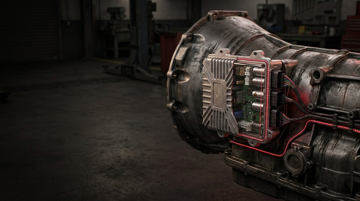
As automated transmissions have become standard on heavy commercial vehicles, workshops have seen a steady rise in trucks arriving with complaints such as "it won't shift", "it dropped into neutral on a grade" or "the N symbol flashes at key-on". In a large share of these cases the transmission control unit is the first component blamed; yet field experience shows that the unit itself is far less often at fault than supply voltage, ground and connector-related issues. This guide explains, in workshop language, what the transmission control unit does, how to determine whether it is genuinely faulty, how replacement and teaching (adaptation) are carried out, and which field habits shorten a unit's life.
This document has been prepared by the VADEN technical team on the basis of field service feedback and catalogue data. The values given here are indicative; for exact torque, pressure, resistance and software/parameter figures, always refer to the current service manual of the vehicle and transmission manufacturer. Last updated: September 2026.
Vehicle electronic equipment such as the transmission control unit falls under ISO 16750, which defines environmental conditions and testing, and ECE R10, which governs electromagnetic compatibility type approval.What Is a Transmission Control Unit (TCU)? Function and Operating Principle
The transmission control unit (TCU) is the electronic control module that, on heavy commercial vehicles, manages gear selection, the clutch and the shift actuators according to sensor data; it communicates with the engine control unit and the braking/retarder systems over the CAN bus to engage the right gear at the right moment.
Its operating principle is essentially a closed loop: the unit builds a picture from the input and output speed sensors, the gear lever/selector position sensors, the clutch travel sensor, the accelerator pedal position and from the engine torque, road speed, braking and gradient data arriving over CAN. Based on this picture it drives pneumatic or electro-hydraulic actuators, requests torque reduction from the engine during the shift, closes the clutch once synchronisation is complete and then verifies the result again through the sensors. If the expected position cannot be confirmed within a defined time window, the unit logs a fault, blocks the relevant function and, in most systems, puts the vehicle into "limp home" (restricted operation) mode.
On automated manual transmissions (AMT) the unit is usually integrated into or mounted close to the transmission housing; on full automatics with a torque converter it may be a separate box inside the cab or on the chassis. In both architectures the peripheral components connected to the unit are largely the same.
- Microcontroller and power stage: Decision logic, valve/solenoid drivers and current protection circuits.
- Speed sensor inputs: Transmission input, countershaft and output speed (inductive or Hall type).
- Position sensors: Gear selector, lever position, clutch travel and, in some systems, actuator stroke sensor.
- Actuator outputs: Pneumatic solenoid valves (gate/selector/split/range), clutch actuator, oil pump or pressure valves.
- CAN interfaces: Vehicle CAN (engine, brakes, retarder, instrument cluster) and, in some systems, a separate internal transmission sub-CAN bus.
- Supply and ground: Permanent 24 V supply, ignition-switched supply and a low-resistance chassis ground.
- Non-volatile memory: Adaptation values, wear compensation, vehicle configuration and fault records.
Why is adaptation (learning) so critical?
The unit continuously learns and compensates for the shift in the clutch engagement point as the friction lining wears, for mechanical tolerances in actuator stroke and for synchroniser wear. These learned values live in the unit's memory; when the unit is replaced or the memory is reset, the system starts from "zero knowledge". If the vehicle is put back on the road without adaptation, clutch engagement becomes harsh, and juddering on take-off and rolling back on grades appear. A significant proportion of the "I fitted a new unit and it still isn't right" complaints in the field are in fact adaptation procedures that were never carried out or left half-finished.
Pneumatic versus electro-hydraulic architecture
On European heavy tractor units, pneumatic actuation is the common AMT solution: the unit drives solenoid valves and air cylinders perform the movement. In this architecture, air quality directly affects the health of the unit; moist or oily air damages the valve block, and the unit then keeps feeding current to a defective valve, stressing its output stage. In electro-hydraulic and torque-converter systems, pressure control is handled by proportional solenoids; here oil temperature and oil quality are decisive. In both cases the unit cannot be considered independently of the health of the hydraulic or pneumatic system connected to it.
Relationship with the engine control unit
Gear shifting is not the transmission's job alone. During a shift the unit requests torque reduction from the engine control unit; if the engine side responds late or not at all, shifts become harsh, synchronisers are overloaded and, over time, "shift time exceeded" type faults accumulate. For this reason, reading the engine-side fault records before looking at the transmission fault codes shortens diagnostic time considerably.
| System / architecture | Typical application | Actuation | Unit location | Critical maintenance point |
|---|---|---|---|---|
| AMT — pneumatically actuated (ZF type / equivalent) | Heavy tractor units, long haul, 4x2 and 6x2 | Compressed air + solenoid valve block | On the transmission housing | Air dryer and moisture draining |
| AMT — pneumatic, with split/range groups (equivalent with Knorr type valve components) | Construction, rigid dump trucks, heavy tractors | Air cylinder + range valve | On the transmission housing | Valve block sealing, air quality |
| Full automatic, torque converter | City buses, fire appliances, concrete mixers | Electro-hydraulic, proportional solenoid | Separate box (cab/chassis) | Transmission oil and filter interval |
| Retarder-integrated systems (Voith type / equivalent) | Buses, heavy haulage, gradient routes | Hydrodynamic brake + transmission control | Common or separate unit | Cooling circuit and oil temperature |
| Manual with automated clutch (semi-automatic) | Distribution, medium-duty trucks | Electro-pneumatic clutch actuator | Under cab / chassis | Clutch wear adaptation |
Part number verification is essential. Transmission control units differ according to transmission type, gear ratio, axle ratio, presence of a retarder, PTO configuration and software level. Two units with identical external appearance and connector layout may belong to entirely different configurations. Before ordering, the transmission type plate, the vehicle chassis number and the OE number on the existing unit must be confirmed together. A unit fitted despite a number mismatch will, in most systems, either fail to communicate at all or run with incorrect ratios and cause synchroniser and clutch damage.
Fault Symptoms and Diagnosis
Transmission control unit faults rarely appear with a single symptom. Typically an intermittent behavioural fault comes first, followed by a permanent fault and restricted operation mode. The diagnostic sequence is fixed: supply and ground first, then connectors and wiring, then live data from sensors and actuators, and only last the unit itself.
| Symptom | Possible cause | Check / verification |
|---|---|---|
| Constant "N" or blank gear display with ignition on, vehicle will not move | No supply to the unit / broken ground / blown fuse | Measure ignition and permanent supply voltage at the unit connector under load; check ground resistance against the chassis |
| Diagnostic tool cannot connect to the transmission unit at all, while other units respond | Broken or short-circuited CAN bus, terminating resistor issue, internal unit fault | Measure resistance between CAN-H and CAN-L with the ignition off, isolate any bus short; only suspect the unit after the supply has been confirmed |
| Clutch engages harshly on take-off, the vehicle judders or rolls back on grades | Clutch adaptation lost or incomplete, wear compensation at its limit | Read the engagement point and clutch wear percentage in live data; run the adaptation procedure and verify the result again |
| One particular gear will not engage while the others are normal | Faulty solenoid valve or position sensor for that gate, mechanical binding | Actuate the valves one by one with the actuator test; measure coil resistance and follow the position sensor signal through its full stroke |
| Shifts are delayed, engine speed hangs during the shift | Delayed torque reduction response from the engine side, low air pressure or CAN latency | Read engine and transmission fault records together; monitor system air pressure and the pressure drop at the moment of the shift |
| Vehicle in restricted mode, driving in only a few gears | Unit has entered safety mode; speed sensor or actuator feedback inconsistent | Retrieve active and stored fault codes; compare input and output speed sensor signals on the road (ratio plausibility) |
| Faults occur when the vehicle is used in wet or high-vibration conditions but cannot be reproduced in the workshop | Water/moisture ingress into the connector, oxidised pin, damage to the wiring harness | Disconnect the connector and inspect pin surfaces and seal/gasket condition; move the harness while watching live data for signal dropouts |
| Gears remain locked after the engine is shut down, the unit powers down late after key-off | Permanent supply (terminal 30) problem, the unit cannot complete its shutdown routine | Check the permanent supply fuse and line voltage; question the habit of cutting power with the battery master switch |
Electrics first, electronics second
The most common mistake in diagnosing unit faults on heavy commercial vehicles is going straight to parts replacement as soon as the words "control unit" appear in a fault code. The unit also behaves inconsistently when its supply voltage drops or its ground resistance rises, and it may report this as if it were an internal fault. Voltage collapse during cranking, a loose battery terminal, oxidation at an auxiliary ground point — all of them imitate a unit fault. Measurements must therefore be taken under load, while cranking and while actuators are operating, not on an unloaded circuit.
No decision without live data
A fault code is a starting point, not a conclusion. Whether input speed and output speed progress in line with the gear ratio, whether the clutch travel sensor delivers an uninterrupted curve across its stroke, and whether the valves draw current on command must be observed on the road or with the drive axle raised. If the unit issues the correct command but no feedback arrives, the problem lies further down the line, not in the unit.
When is a unit fault confirmed?
If supply and ground measurements are normal, CAN communication with the other units is healthy, sensor and actuator resistance/signal values are within the manual's range and there is no oxidation on connectors or wiring — yet no current or voltage appears at the output when the unit issues a command, or the unit reports an internal fault repeatably — then the case for replacement has been made. A replacement carried out before this verification chain is complete usually reproduces the same fault with a new part.
Further reading
For a plain-language technical overview of this subject, see the reference article on Wikipedia. Always confirm specific figures and procedures against the vehicle manufacturer service data.
Replacement / Installation Steps
Personal protective equipment and safety. The vehicle must be on level ground with the parking brake applied, wheels chocked and the transmission left in neutral. Work gloves and safety glasses are mandatory. When working on an electronic unit, take electrostatic discharge precautions (grounding wrist strap). The transmission and its oil may be hot; allow them to cool. On pneumatic systems, air pressure must be reduced to a safe level in accordance with the manufacturer's instructions. Welding, battery charging or disconnecting the supply can damage the unit; the manufacturer's instructions are decisive.
- Document the fault: Before replacement, read and record the fault memories of all units, live data snapshots, and adaptation and configuration values. This record is needed both for the warranty process and for comparison should the problem recur.
- Confirm part suitability: Compare the transmission type plate, the OE part number, the software/hardware level and the vehicle chassis number. Differences in axle ratio, retarder and PTO configuration must be noted.
- Make the vehicle electrically safe: Switch off the ignition, wait for the period specified by the manufacturer (so the units can complete their shutdown routine), then disconnect the battery negative terminal or the master switch as instructed.
- Release pressure and drain fluid: On pneumatic systems, reduce air pressure to a safe level; on hydraulic/torque-converter systems, if removing the unit will cause oil loss, prepare a suitable container and record the level and condition of the oil.
- Mark and disconnect the connectors: Number or photograph multi-pin connectors. Do not force the locking tabs; a broken tab means poor contact and a repeat fault later on. Inspect the pin surfaces as you disconnect.
- Remove the unit and inspect the mounting face: Loosen the fasteners progressively. Inspect the gasket/seal face beneath the removed unit for corrosion, moisture traces and oil leakage. If there are traces of moisture, no new unit should be fitted until the source has been eliminated.
- Repair wiring and ground: Any chafing, crushing, burning or oxidised pins in the harness must be rectified before the new unit is fitted. Clean the ground point and measure its resistance. If this step is skipped, the new unit will be damaged the same way.
- Fit the new unit: Position the unit and gasket face clean and dry, and tighten the bolts to the manufacturer's torque figure progressively in a cross pattern. Overtightening can crack the housing; a loose installation leads to solder joint fatigue through vibration.
- Connect and lock the connectors: Seat the seals correctly and make sure the locking tab engages fully with an audible click. Secure the harness on its original route and in its original clips; an unsecured harness is the most frequent cause of repeat faults.
- Load configuration and software: Once the supply is reconnected, use the diagnostic tool to load the vehicle configuration (transmission type, axle ratio, tyre size, retarder/PTO) and, if required, bring the software level into line with the vehicle. This step requires a manufacturer-specific procedure.
- Adaptation and road test: Carry out the clutch engagement point, actuator stroke limit and gear position learning procedures in full. Then, on a laden or unladen road test, try all gears, reverse, a hill start and retarder engagement. At the end of the test, read the fault memory again and confirm that it is empty.
Points to Watch (Common Mistakes)
Protect the unit before welding. If electric arc welding is to be carried out on the chassis, the battery connections must be disconnected according to the manufacturer's instructions and the welding earth clamp attached as close as possible to the point being worked on. Welding current passing through the transmission unit usually leaves permanent damage that appears not immediately but weeks later.
Jump-starting and fast-charging risks. Jump-starting with reversed polarity causes irreversible damage to the unit. High-current fast chargers must not be used on the vehicle while the control units are connected. Voltage collapses during prolonged cranking attempts with a weak battery can also cause the unit to generate spurious fault codes and corrupt adaptation values.
- Skipping adaptation: The "it drives, we'll do it later" approach rapidly consumes the clutch lining and the synchronisers. Adaptation must be completed on the same day, as part of the replacement.
- Fitting a unit without copying the configuration from the old one: A unit with the wrong axle ratio or tyre size runs at the wrong engine speed in the correct gear; fuel consumption rises and shifts become harsh.
- "Cleaning" a connector with compressed air or contact spray and leaving it at that: If the problem is an oxidised pin, spray gives a temporary improvement and the fault returns within a few weeks. The defective pin/terminal must be replaced.
- Not eliminating the source of water ingress: Aiming a high-pressure washer directly at the connector, a broken clip or a split boot will destroy one unit after another.
- Ignoring air quality: In a system whose dryer cartridge is past its service life, moist air reaches the valve block; the unit constantly compensates and wears out its output stage.
- Replacing parts on the basis of the fault code alone: The code identifies the circuit, not the address of the fault. A replacement made before the verification chain is complete risks creating a second faulty part.
- Failing to secure the harness on its original route: An unsecured harness is exposed to exhaust heat or chafing; after a few thousand kilometres it produces leakage currents and intermittent faults.
- Cutting the master switch immediately after switching off the ignition: The unit cannot complete its shutdown routine; adaptation and fault records are written incompletely. The waiting time specified by the manufacturer must be observed.
Technical Values and Check Points
The values below are typical ranges frequently encountered in heavy commercial vehicle applications and are given for general reference only. They vary by system, make and model; for measurement and adjustment work, the vehicle manufacturer's current service manual is decisive.
| Check point | Typical range (general reference) | Measurement condition / note |
|---|---|---|
| Unit supply voltage (24 V system) | approx. 24–28 V | Ignition on, engine running; measured under load |
| Minimum acceptable voltage during cranking | generally above 18 V | Below this the unit may generate transient faults |
| Ground resistance (unit ground pin to chassis) | typically below 1 Ω, around 0.5 Ω in most applications | Measured including cable and contact resistance |
| Resistance between CAN-H and CAN-L (ignition off) | approx. 60 Ω (two 120 Ω terminators in parallel) | If only 120 Ω is read, a terminator or the bus may be open |
| Pneumatic solenoid valve coil resistance | usually in the 20–60 Ω band | Varies with temperature; compare with the manual value |
| System air pressure (AMT actuation) | approx. 8–12.5 bar (approx. 115–180 psi) | The momentary drop during a shift should also be monitored |
| Transmission oil operating temperature | typically 70–100 °C; higher under heavy pulling | The warning threshold is set by the manufacturer |
| Oil over-temperature warning zone | generally above 120 °C | On retarder systems, check the cooling circuit |
| Unit ambient operating temperature | approx. –40 °C to +85 °C band | Transmission-mounted units run closer to the upper limit |
| Clutch wear indicator (live data) | usually a 0–100% scale; above 80% signals planned maintenance | The value should be read after adaptation |
| Joint | Typical torque range (general reference) | Note |
|---|---|---|
| Unit mounting bolts (M6) | approx. 8–12 Nm | Tightened progressively in a cross pattern |
| Unit mounting bolts (M8) | approx. 20–28 Nm | Overtightening risks cracking an aluminium housing |
| Ground cable lug (M8) | approx. 15–25 Nm | The contact face must be clean and free of paint |
| Speed sensor retaining bolt | approx. 8–15 Nm | Air gap is checked against the manufacturer's value |
| Valve block retaining bolts | approx. 10–20 Nm | The gasket face must be loaded evenly |
Torque and resistance values are intended only to give an idea of the order of magnitude. Because different values may be used within the same transmission family across production years, the current service manual figure for the specific vehicle must be used for tightening and measurement. Using a calibrated torque wrench and a multimeter with valid calibration visibly reduces the repeat-fault rate.
- Are there traces of moisture, salt or oil on and around the unit connector?
- Is the wiring harness on its original route with all its clips fitted?
- Does supply voltage drop below the acceptable level during cranking?
- Is the air dryer cartridge overdue, and is water drained from the reservoirs?
- Are the transmission oil level, colour and change interval correct?
- Do the clutch wear percentage and engagement point match the recorded values?
- Are there any torque-reduction related fault records in the engine control unit?
- On the road test, are all gears, reverse and hill starts trouble-free?
Maintenance and Service Life
The transmission control unit is not a consumable replaced at set intervals; under the right conditions it is expected to last the economic life of the vehicle. What determines its service life is far less its own quality than the environment it is exposed to: voltage fluctuations, moisture, vibration, temperature and the health of the pneumatic or hydraulic system it is connected to. Units that fail early in the field almost always have one of these five headings in common.
- Battery and charging system maintenance: Clean terminals, tight cable lugs and alternator output checks directly extend unit life.
- Checking ground points: At least once a year, ground connections should be disconnected, cleaned and given suitable corrosion protection.
- Air system maintenance: The dryer cartridge must be replaced at its service interval and water drained regularly from the air reservoirs. Dry air is the cheapest insurance a valve and a unit can have.
- Transmission oil and filter: Oil of the manufacturer's specification must be used at the specified interval. Overheated oil disturbs the behaviour of proportional solenoids and forces the unit into constant compensation.
- Connector and harness checks: At periodic service, the connector lock, seal and harness routing should be inspected visually.
- Washing discipline: High-pressure water must never be aimed directly at the unit or its connectors.
- Software level: Updates released by the manufacturer may contain known shift quality and fault management improvements; they should be queried during major services.
- Adaptation follow-up: Adaptation must always be renewed after a clutch replacement, actuator removal or transmission overhaul.
In short, maintaining the unit really means maintaining the system around it. Clean air, a sound ground, stable voltage and the correct oil — with these four in place, a transmission control unit will run for many years in heavy commercial service without causing trouble. For fleets, adding these items to the periodic maintenance card is the lowest-cost way of reducing unplanned roadside stoppages.
On the transmission control side VADEN ORIGINAL offers from stock, for heavy commercial vehicle applications, the pneumatic shift-control components: Range Change Valves and their Repair Kits, Gearbox Housing Valves, Gearbox Housing Solenoid Valves and Gearbox Housing Repair Kits, and Lever Actuators with their Repair Kits. The electronic control unit itself is sourced through the vehicle and transmission manufacturer's own catalogue; to identify the right part for your vehicle, you can review our product family using the chassis number, the transmission type plate and the existing OE number, and request support from the VADEN technical team for matching.
Related categories: Gearshifting Control · Gearshifting Control · Repair Kit
Related technical guides: Truck Retarder: Faults, Replacement & Maintenance Guide · Heavy-Duty Truck Gearbox: Faults, Replacement & Maintenance · Transmission Shift Cylinders: Failure, Replacement & Care · Transmission Shift Tower: Faults, Replacement & Maintenance
Application and compatibility: Vehicle compatibility catalogue · Engine compatibility catalogue
Tags
Frequently Asked Questions
- What is the most obvious symptom of a transmission control unit fault?
- The most common picture is a vehicle that cannot complete gear shifts and drops into restricted operation mode. This is usually accompanied by a transmission warning lamp on the instrument cluster, a blank or fixed "N" on the gear display and active transmission fault codes on the diagnostic tool. However, since the same symptoms also occur with supply, ground and connector problems, a unit fault can only be confirmed once the verification chain is complete.
- Is it mandatory to load software and run adaptation after replacing a TCU?
- Yes. A new unit knows neither the vehicle configuration nor the learned adaptation values. The vehicle must not be returned to service until the transmission type, axle ratio, tyre size, retarder and PTO data have been loaded and the clutch engagement point and actuator stroke learning have been completed. Skipping these steps makes shifts harsh and wears the clutch and synchronisers rapidly.
- Can the vehicle be driven with a faulty transmission control unit?
- Moving a short distance in restricted mode is possible on most systems, but this is a way of getting the vehicle to a safe place, not a way of operating it. Unexpectedly dropping into neutral, rolling back on a grade or being unable to shift all pose serious road safety risks. Laden and long-distance operation is not advised until the fault has been rectified.
- Can a transmission control unit be repaired, or must it be replaced?
- Repair may be considered for superficial issues such as a connector pin or a cracked solder joint; however, on a heavy commercial vehicle the unit is a control element that directly affects vehicle safety. For software integrity, configuration compatibility and long-term reliability, complete replacement with a unit of the correct specification is preferred for confirmed faults.
- Can a second-hand unit or one removed from another vehicle be fitted?
- It is not recommended. A second-hand unit carries the configuration and adaptation history of the vehicle it came from, and in many systems it may be locked to a chassis number. An incorrect axle ratio or a different software level creates a system that looks right but works wrongly. A new unit with a verified part number works out cheaper in total cost.
- Does clearing the fault code make the fault go away?
- Clearing a fault code only erases the record, not the cause. If the cause persists, the code will return within a short time. Codes should only be cleared for verification purposes after the physical repair is complete, followed by a road test confirming that the code has not returned.
- What damages a transmission control unit?
- The most common causes seen in the field are: jump-starting with reversed polarity, arc welding carried out with the control units connected, water/moisture ingress into the connector, oxidised grounds and pins, voltage collapses caused by a weak battery, valve faults caused by moist air overloading the unit, and vibration fatigue caused by loose mounting or an unsecured harness.
- How do I select the correct transmission control unit?
- The vehicle chassis number, the transmission type plate and the OE number on the existing unit must be used together. Selecting on make and model alone is risky, because the same vehicle may be built with different transmission and ratio combinations. Retarder, PTO and axle ratio differences must also always be stated.
- I fitted a new unit but the same fault came back within weeks. Why?
- Usually because the environment around the unit was never repaired. A replacement made before the verification chain is complete reproduces the same fault with a new part: a chafed harness or oxidised pins, a high-resistance ground point, an unresolved source of moisture in the connector and an unsecured harness will damage the new unit the same way. Configuration not loaded or a half-finished adaptation also brings the vehicle back with the original complaint.
- Does adaptation have to be renewed even when the control unit itself is not replaced?
- Yes. Adaptation must always be renewed after a clutch replacement, actuator removal or transmission overhaul. The unit learned the clutch engagement point, actuator stroke limits and gear positions from worn hardware, so those values no longer match the new parts. Running on the old values makes engagement harsh, produces juddering on take-off and rolling back on grades, and consumes the new clutch lining quickly.
Related Articles
Transmission PTO: Faults, Replacement and Maintenance Guide
A workshop guide to truck transmission PTO units: how they work, why they fail to engage, correct backlash setting on fitting and habits that extend life.
Transmission Housing Repair Kit & Valve: Faults & Replacement
Understand how the pneumatic shift valve and its seal kit work, spot air leaks early, replace the parts correctly and extend service life on trucks.
Transmission Shift Tower: Faults, Replacement & Maintenance
Transmission shift tower faults, diagnosis, replacement steps, torque and pressure values, maintenance and FAQ for heavy commercial vehicles — VADEN guide.


