Transmission Housing Repair Kit & Valve: Faults & Replacement
Understand how the pneumatic shift valve and its seal kit work, spot air leaks early, replace the parts correctly and extend service life on trucks.
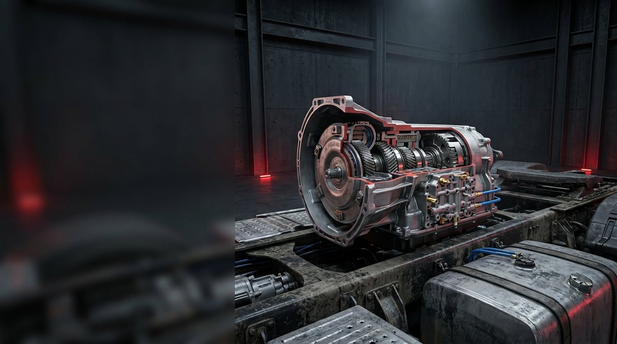
When a tractor unit refuses to select a gear, will not change range or drops out of gear on a climb, the first component blamed is always the gearbox itself. In reality, most of the faults that are solved in the field without opening the housing come down to the pneumatic control valve mounted on the transmission case and to the aged gasket and O-ring set underneath it. A repair kit weighing a few hundred grams can, in the right circumstances, prevent a complete transmission overhaul. This guide explains what the transmission housing repair kit and valve do, which symptoms point to a failure, the correct diagnostic sequence, the discipline required for removal and refitting, and the maintenance habits that extend service life, all from a workshop technician's point of view.
What Is a Transmission Housing Repair Kit & Valve? Function and Operating Principle
The transmission housing repair kit and valve form the service group made up of the gaskets, O-rings, oil seals, piston and spring components that keep the pneumatic gear shift and range mechanisms on the body of a heavy commercial vehicle transmission leak-tight, together with the valve that controls gear selection using 6–8.5 bar supply air; typical service life is in the range of 300,000–600,000 km depending on operating conditions.
In a heavy commercial vehicle transmission, the driver's arm strength alone does not engage the gear. The lever or the electronic control unit generates a request, this request reaches the valve on the transmission case, and the valve directs the pressure coming from the vehicle air system to the correct side of the correct cylinder. The cylinder piston pushes the shift fork, the synchroniser engages and the shift is completed. In other words, the valve is a decision-making element, while the repair kit is the sealing chain that ensures that decision is carried out by the air without losses.
The lifeblood of the system is pressure stability. Transmission pneumatics are fed from the auxiliary consumer circuit that comes after the brake circuits; because the four-circuit protection valve gives priority to the brake circuits within the ECE R13 framework, any weakness on the compressor or air dryer side shows itself first in gear shifting. This is the picture most frequently encountered in the field: the brakes hold, but the transmission shifts late.
What does the control valve do?
The transmission housing valve is the directional control element that converts the incoming signal into pneumatic flow. In mechanically operated gearboxes the signal is a pilot air feed coming directly from the gear lever; in electro-pneumatic gearboxes a solenoid coil energised by the transmission control unit opens a small pilot valve and the main spool changes position. The position of the spool determines which chamber of the cylinder fills and which one empties. The exhaust port in the valve body rapidly vents the opposing chamber once the shift is complete; if this port becomes blocked, the shift is left "half done".
Which components make up the repair kit?
- Piston O-rings and back-up rings: the main elements that separate the cylinder chambers and determine leakage.
- Body and cover gaskets: oil and air sealing between the valve body and the transmission case.
- Shaft seals and wipers: prevent oil escaping outwards and dirt entering at the shift shaft exit.
- Spring set: returns the spool and the piston to the neutral position; when fatigued, shifting is delayed.
- Piston and spool (application-dependent): replacements for elements with scored or worn surfaces.
- Filter element and silencer: against contamination at the exhaust port.
- Locking pin, circlip and retaining elements: small parts that should be treated as single-use items.
The material class of the elastomers in the kit matters. Because they operate in an environment where transmission oil, heat and condensation water are present together, elements based on NBR or FKM with a hardness band of 70–90 Shore A are generally preferred in manufacturing. O-ring size and tolerance families are defined within the ISO 3601 / DIN 3771 framework; however, every application has its own dimension table and the exact match must be verified from the OE catalogue for the part.
Which transmission families is it found on?
Pneumatically operated gear shifting is almost standard on heavy commercial vehicles, so the transmission housing repair kit and valve are spread across a very wide application range. The table below summarises how differences in type change the service approach. Brand names are given only as application examples; the correct part is determined not by brand but by the transmission type code and the OE number.
| Transmission family / control type | Valve function | Typical supply pressure | Service note |
|---|---|---|---|
| Mechanically operated multi-speed gearboxes (ZF Ecosplit type 16-speed applications) | Splitter and range directional control valve, with pilot air | 6–8.5 bar | The repair kit can usually be fitted without opening the housing |
| Automated gearboxes (ZF AS Tronic / TraXon type) | Electro-pneumatic module with solenoid block | 6–8.5 bar | Calibration/teach-in may be required after replacement |
| Mercedes-Benz G / GO series applications | Range and splitter cylinder control | 6–8.5 bar | Renewal together with the cover gasket is recommended |
| Volvo and Scania automated gearboxes | Integrated valve block on the module | 6–8.5 bar | Fault codes and pneumatic leakage are assessed together |
| Eaton type gearboxes with range/splitter unit | Separate range valve and cylinder | 5.5–8 bar | The cylinder cover and piston surface must always be inspected |
How do you recognise a Transmission Housing Repair Kit & Valve failure?
Transmission housing repair kit and valve failures fall into two main groups: air escaping, and air going to the wrong place. The first reduces shift force, the second prevents the shift altogether. The table below matches field symptoms with probable causes and verification methods.
| Symptom | Probable cause | Check / verification |
|---|---|---|
| Shifting has become slow, the lever is stiff or the shift is left half done | Piston O-ring fatigued, internal leakage inside the cylinder | Supply pressure is measured with a gauge; the system is held at around 6 bar and a pressure drop test is carried out |
| Range does not change; the high or low group cannot be engaged | Valve spool seized, exhaust port blocked or solenoid not being supplied | Measure supply voltage at the connector and coil resistance; listen for air venting from the exhaust port |
| Constant sound of air leakage, compressor cutting in more frequently | Body gasket or shaft seal torn, fitting loose | Leak search with soapy foam while the engine is running; monitoring the air dryer purge frequency |
| Oil seepage from the transmission case, oil traces around the valve | Oil-side sealing on the valve-to-case gasket has failed | Clean the surface and re-inspect after a short road test; check the oil level |
| Shifting is troublesome when cold and improves as the engine warms up | Hardened elastomers and condensation water/icing in the system | Drain the air tanks and dryer; assess the age of the dryer cartridge and the dew point |
| Transmission warning on the instrument cluster, vehicle enters limp-home mode | Position/pressure signal in the electro-pneumatic module is not reaching the expected value | Read fault codes and live data with a diagnostic tester; monitor the cylinder position sensor data during the shift |
| No problem at idle, but shifting disappears under load and on gradients | Supply pressure drops under load; protection valve or compressor capacity is weak | Dynamic pressure measurement under load; reading the brake circuits and the auxiliary circuit separately |
How is the pressure drop (leakage) test performed?
The method that reveals transmission housing repair kit and valve leakage most honestly is the static pressure drop test. The system is brought up to working pressure, the engine is stopped and the gauge connected to the transmission supply line is observed for a few minutes; on a sound circuit the drop is too small to measure. If there is a noticeable drop, the line, the valve and the cylinder are isolated in turn to narrow down the source. Repeat the test under both hot and cold conditions; a hardened O-ring may leak only when cold.
Reading fault codes and live data on electro-pneumatic gearboxes
On automated gearboxes, every interpretation made without a diagnostic tester is guesswork. After reading the fault code, look not at the code itself but at the live data at the moment of the shift: has the request signal arrived, is the solenoid energised, has the position sensor seen movement? If there is a signal but no movement, the problem is on the pneumatic side and the repair kit and valve are the first candidates. If there is no signal at all, the wiring, connector and supply should be checked first.
Visual and audible checks that can be made without dismantling
Exhaust the cheap checks before opening the housing. A build-up of oil and dust paste around the valve is a classic sign of gasket leakage. If air comes continuously from the exhaust port, there is internal leakage. Look for crushing, cracks or chafing marks on the air lines; the top of the transmission is the area with the highest vibration. Finally, open the air tank drain valve and look at the water that comes out: plenty of water shows that the dryer is not doing its job.
Other interfaces bolted to the same housing can leave a similar trace; to tell the power take-off's gasket face apart, see the transmission PTO faults, replacement and maintenance guide.
Further reading
For a plain-language technical overview of this subject, see the reference article on Wikipedia. Always confirm specific figures and procedures against the vehicle manufacturer service data.
How is a Transmission Housing Repair Kit & Valve replaced? Step by step
Transmission housing repair kit and valve replacement, when carried out in the correct sequence, is not a roadside repair but neither is it a long workshop job. What matters is the discipline of depressurising, cleanliness and torque control.
- Secure the vehicle and prepare: chocks, parking brake, ignition off. Photograph the transmission type plate; part verification is made from this plate.
- Depressurise the air circuit: drain the tanks and confirm with a gauge that no pressure remains in the transmission supply line. "No sound" is not sufficient proof.
- Mark and disconnect the connections: number or photograph the air hoses and the electrical connector. Two lines connected the wrong way round means a range group that works in reverse.
- Clean the surrounding area: remove the oil and dust deposits around the valve and cover before dismantling. A single grain of sand that gets inside will score the new O-ring on the first cycle.
- Remove the valve and cover: loosen the bolts in a crosswise sequence. The cover may be spring-loaded; separate it in a controlled manner and record the arrangement of the spring, piston and washers underneath.
- Assess the removed parts: look for scoring on the cylinder bore, wear on the piston and scuffing in the spool bore. If the surface is damaged, replacing the O-rings alone will not be a lasting solution.
- Prepare the seats and surfaces: remove old gasket residues with a soft scraper. Do not apply abrasive paper or grinding to the case surface; you will destroy its flatness.
- Fit the new kit components: lightly lubricate the O-rings with transmission oil or a suitable assembly grease and slide them over sharp edges without forcing. A twisted or kinked O-ring will leak.
- Seat the valve and tighten to torque: start the bolts by hand and tighten them crosswise in two stages with a torque wrench. The torque value must be taken from the OE manual.
- Reconnect the lines and connector: connect according to your markings and make the fittings leak-tight without overtightening. Clamp the wiring harness to fixed points away from vibration.
- Pressurise, test and complete: bring the system up to working pressure, carry out a leak test and check the oil level. On electro-pneumatic gearboxes, clear the fault codes and, if required, perform the calibration/teach-in procedure, then carry out a short road test covering all gear and range shifts.
What are the most common mistakes when replacing a Transmission Housing Repair Kit & Valve?
Transmission housing repair kit and valve replacement errors that keep recurring stem mostly from method rather than from the part. The three most frequently encountered in the field are these: removing the cover before the pressure has been fully released, replacing only the leaking element and leaving the others of the same age in place, and tightening by "feel" instead of using a torque wrench.
- Choosing the wrong variant: within the same transmission family there are kits of different dimensions; the selection must be made using the type code and the OE number.
- Fitting the O-ring dry: an unlubricated element twists or is cut during assembly; it looks fine on the first day and leaks soon after.
- Reinforcing with sealant: sealant applied over a gasket can squeeze out and block the air channel and the exhaust port.
- Overtightening: stripping a thread in the aluminium housing is a more expensive mistake than crushing a gasket and creating a leak.
- Connecting the air lines the wrong way round: the range group then works in reverse; always mark them before dismantling.
- Continuing with a dirty air supply: in a system with an exhausted dryer, the new kit will die at the same age.
- Reusing single-use elements: retaining circlips, locking pins and washers must be renewed if they come in the kit.
Transmission Housing Repair Kit & Valve technical values and check points
The transmission housing repair kit and valve figures below show the bands typically encountered in heavy commercial vehicle applications; the exact data is in the vehicle's own service manual.
| Parameter | Typical value range | Note |
|---|---|---|
| System air pressure (auxiliary circuit) | 8–10 bar (116–145 psi) | Cut-out pressure varies with the compressor governor |
| Transmission control working pressure | 6–8.5 bar (87–123 psi) | The value that determines shift force |
| Minimum pressure for reliable shifting | Approximately 5.5–6 bar | Below this, shifting slows down or is left half done |
| Static leak test (5 minutes) | No measurable drop expected; typical acceptance limit below 0.2 bar | The limit value must be verified from the OE manual |
| Gear/range shift time | Approximately 0.3–1.2 s | An increase indicates internal leakage or a restriction |
| Transmission oil working temperature | 80–120 °C, above 130 °C under peak conditions | Directly affects elastomer service life |
| Elastomer operating temperature band | Approximately -40 °C to +120 °C | Varies with material class (NBR / FKM) |
| O-ring hardness | 70–90 Shore A | Size families are defined within the ISO 3601 / DIN 3771 framework |
| Solenoid coil supply voltage | 24 V DC system | The resistance value is application-specific; OE data takes precedence |
| Compressed air quality | Dry and oil-free according to the ISO 8573-1 classification | The dryer cartridge must be renewed periodically |
| Connection | Typical torque range | Application note |
|---|---|---|
| Valve body retaining bolt M6 | 8–12 Nm | Crosswise sequence, in two stages |
| Valve body retaining bolt M8 | 20–28 Nm | The upper limit must not be exceeded on an aluminium body |
| Cylinder cover bolt M10 | 40–55 Nm | Stepped tightening on spring-loaded covers |
| Air line fitting (M12x1.5 / M16x1.5 class) | 15–30 Nm | Port thread families are covered by ISO 6149 / DIN 3852 |
| Position/pressure sensor | 25–35 Nm | Overtightening cracks the sensor body |
| Drain/exhaust silencer element | Hand tight + a quarter turn | A torque wrench is not used on plastic bodies |
Check points that can be applied in the field:
- Read the pressure in the transmission supply line with the engine at idle; if it is below the working band, look at the source (compressor, dryer, protection valve).
- Stop the engine and carry out a 5-minute static drop test; if there is a noticeable drop, narrow it down by isolating the circuit.
- Listen at the exhaust port: if air comes continuously outside of a shift, there is internal leakage.
- Check on a clean surface whether oil and dust paste is building up around the valve.
- Measure the shift time and compare it with the previous service record; an increase is an indicator of silent deterioration.
- Assess the water that comes from the air tank drain; if there is water, schedule the dryer cartridge.
How is a Transmission Housing Repair Kit & Valve maintained and its service life extended?
The transmission housing repair kit and valve service life is determined above all not by the part itself but by the quality of the air feeding it. In a system where the dryer does its job and the tanks are drained regularly, the elastomers work close to the upper band; the same part will not last half as long in a system carrying water and oil. For that reason, transmission pneumatics maintenance should be kept in the same book as air treatment unit maintenance.
- Put the air dryer cartridge on a schedule: renew it at the interval recommended by the manufacturer, and earlier in heavily dusty and humid climates.
- Drain the tanks regularly: recording the amount of water that comes out is the cheapest data you can get about the condition of the dryer.
- Monitor compressor and governor performance: if the charging time is getting longer, gear shifting will soon be affected too.
- Check the transmission oil and its level at the OE interval: low level and excessive temperature are the real factors that shorten seal life.
- Clamp the air lines against vibration: when you see a chafing mark on the lines above the transmission, renew the pipe without delay.
- Replace the kit as a whole: renewing elastomers of the same age piece by piece means repeat service visits at short intervals.
- Keep a service record: when shift time, pressure readings and replacement mileage are recorded, the next failure becomes predictable.
The transmission housing repair kit and valve are a low-cost but high-impact maintenance item. When the air system is kept healthy and the replacement is carried out with the correct variant, the correct torque and in a clean environment, this group can work trouble-free throughout the transmission's overhaul interval. A small leak that is postponed, on the other hand, increases compressor load and reduces shift force, opening the door to a far larger repair.
Related categories: Repair Kit · Valve
Main guide: Heavy-Duty Truck Gearbox: Faults, Replacement & Maintenance
Tags
Frequently Asked Questions
- What does a transmission housing repair kit contain?
- A transmission housing repair kit covers the sealing elements of the pneumatic gear shift group: piston O-rings and back-up rings, body and cover gaskets, shaft seals and wipers, the spring set and, depending on the application, the piston, spool, filter element and retaining circlips. The scope of the kit varies with the transmission family; the content list must be verified from the OE catalogue for the part.
- What is the most typical symptom of a transmission valve failure?
- The most typical symptom is the inability to make a range or splitter shift, or a shift that slows down and is left half done. This is usually accompanied by a constant sound of air leakage around the valve and the compressor cutting in more often. On electro-pneumatic gearboxes, a transmission warning on the instrument cluster and a switch to limp-home mode may also be seen.
- At what pressure does a transmission housing valve operate?
- On heavy commercial vehicles the transmission control valve is typically supplied in the 6–8.5 bar range, while the vehicle air system generally works in the 8–10 bar band. For reliable shifting, the supply pressure is expected not to fall below approximately 5.5–6 bar. Exact values are defined in the vehicle's OE service manual.
- Does the transmission have to be removed to fit a repair kit?
- In most applications it does not. The valve, cylinder cover and gasket group on the housing can be serviced without taking the transmission out of the vehicle. However, if damage is found on the cylinder bore or in the shift fork mechanism, or if the fault originates from a component inside the housing, removing the transmission comes onto the agenda.
- Is calibration required after replacing a transmission valve?
- On mechanically operated gearboxes it is generally not required; a pressure and leak test together with a road test is sufficient. On automated electro-pneumatic gearboxes, however, the fault codes may need to be cleared after replacement and the calibration/teach-in procedure defined by the manufacturer applied with a diagnostic tester. Whether it is mandatory depends on the transmission type.
- How often should a transmission housing repair kit be replaced?
- There is no fixed calendar interval; replacement is condition-based. Typical service life is observed in the range of 300,000–600,000 km depending on operating conditions. Humid and dusty working conditions, systems with a neglected air dryer and high transmission oil temperatures shorten this period considerably.
- Why does an air leak disrupt gear shifting?
- Gear shifting is achieved by the pressure difference between the two chambers of the cylinder piston. A leak reduces this difference and therefore the force pushing the shift fork; the shift slows down, is left half done or does not happen at all. A leak also causes the compressor to cut in more often, which in turn increases fuel consumption and compressor wear.
- How is the correct transmission valve selected?
- The selection must be made not by vehicle model but using the code on the transmission type plate, the production number and the OE reference number of the removed part. Within the same transmission family there may be different port threads, O-ring cross sections and electrical connector types depending on the production year and equipment level. In case of doubt, the dimensions of the old part should be compared.
- If oil is leaking from the transmission valve, is the repair kit responsible?
- Generally yes. The intermediate gasket and shaft seal between the valve and the transmission case separate both the air and the oil side; when these elements age, oil seepage becomes visible around the valve. Even so, whether the leak comes from the case surface or from oil running down from points above must be confirmed with a short road test after the surface has been cleaned.
- Why is air quality so important for transmission pneumatics?
- Water and oil in the compressed air harden and swell the elastomer sealing elements and shorten their life; in winter, condensation water can freeze inside the valve and seize the spool. Compressed air quality is classified within the ISO 8573-1 framework, and periodic renewal of the dryer cartridge is the single most effective measure for extending the life of the repair kit.
Related Articles
Transmission PTO: Faults, Replacement and Maintenance Guide
A workshop guide to truck transmission PTO units: how they work, why they fail to engage, correct backlash setting on fitting and habits that extend life.

Transmission Shift Tower: Faults, Replacement & Maintenance
Transmission shift tower faults, diagnosis, replacement steps, torque and pressure values, maintenance and FAQ for heavy commercial vehicles — VADEN guide.

Transmission Control Unit (TCU): Faults, Replacement, Care
Truck TCU guide: fault symptoms, diagnosis order, replacement and adaptation steps, torque and voltage values, plus maintenance tips from VADEN technical.


