Intake Manifold and Intake Pipe: Faults, Diagnosis, Repair
How the intake manifold and charge air pipe work on truck diesel engines, how to spot boost leaks, run a pressure test and fit them leak free.
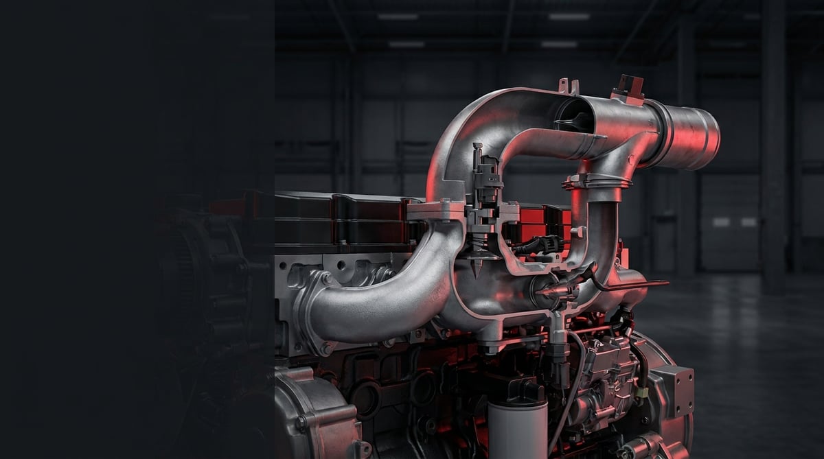
When a heavy commercial vehicle comes in with a power loss complaint, the workshop reflex is usually to look at the turbocharger or the injectors. Yet the most common scenario in the field is far simpler: somewhere along the air path between the turbocharger and the cylinder head, there is a leak. The intake manifold and the intake pipe are the final link carrying the air the engine breathes; a crushed gasket or a loose clamp slows the vehicle on a gradient, darkens its smoke and pushes up fuel consumption. This guide covers the job the intake line does, the character of its faults, the correct diagnostic sequence, removal and refitting discipline, and the maintenance habits that extend its service life.
What Is the Intake Manifold and Intake Pipe? Function and Operating Principle
The intake manifold and intake pipe form the air path assembly consisting of a cast or aluminium body that evenly distributes pressurised air from the turbocharger and intercooler outlet into the intake ports of the cylinder head, together with the connecting pipes feeding that manifold. In heavy commercial diesel engines the intake line typically carries a boost pressure of roughly 2.5–4.5 bar absolute (approximately 1.5–3.5 bar gauge) at full load; air temperature is typically 150–220 °C at the turbocharger outlet and in the 40–70 °C band at the manifold inlet after the intercooler.
The intake manifold and intake pipe are known by several names in the field and in catalogues: inlet manifold, air manifold, turbo outlet pipe, charge air pipe, intercooler pipe and intake elbow. All belong to the same air path family; regardless of the name used to search for them, the selection criteria stay the same: engine code and OE reference number.
The operating principle works like a chain. Clean air passing through the air filter is drawn into the compressor side of the turbocharger, compressed, and leaves at an elevated temperature. The pipe at the turbocharger outlet carries this hot air to the intercooler; the pipe at the intercooler outlet then delivers the cooled, denser air to the intake manifold. The manifold splits a single incoming flow into as many runners as there are cylinders, feeding each cylinder as equally as possible. On Euro 5 and Euro 6 generation engines, this line also carries the EGR mixing point, the intake air temperature and pressure sensor and, in some applications, an intake throttle valve.
The critical point is this: unlike the exhaust side, the intake line operates under positive pressure. An opening here does not draw air in from outside, it lets pressurised air escape. The engine cannot see this loss; it meters fuel according to the pressure it measures and the mixture goes off. In a significant share of vehicles that arrive with a "the turbo isn't boosting" complaint, the turbocharger is sound and the leak is in the pipework.
Manifold body and material differences
In heavy commercial applications the intake manifold body is mostly produced in cast aluminium alloy, in cast iron on some heavy duty engines, and in reinforced composite on sections exposed to lower temperatures. For cast aluminium bodies the EN 1706 casting alloy family and, for general manufacturing tolerances, ISO 2768 classes are taken as reference; this is why the flatness of the sealing face is assessed with a straightedge rather than by eye. The applicable standard and alloy class may vary by engine family, and exact data must be verified from the relevant OE catalogue.
Intake pipes, hoses and clamps
On the intake pipe side three types of construction are seen: rigid aluminium or steel pipe, reinforced flexible hose based on silicone or EPDM, and the sleeve connections that join the two. The hoses between the turbocharger and the intercooler see both heat and pressure, so they are multi-layer braid reinforced. The temperature and pressure class of charge air hoses is defined by the OE specification; on the dimensional side, general hose standards such as ISO 1307 are taken as reference. The connection is usually made with constant torque or spring loaded clamps.
What the turbocharger that compresses the air in this chain does, and the symptoms the driver notices when it fails, are covered in the turbocharger and turbo failure symptoms guide.
Components and ancillary elements
- Manifold body: the main cast part that distributes air to the cylinders.
- Manifold gasket: the sealing element between the body and the cylinder head, usually single use.
- Turbo outlet and intercooler outlet pipes: the lines carrying hot and cooled charge air.
- Reinforced hoses and sleeves: flexible connections absorbing vibration and thermal expansion.
- Clamps and support brackets: elements holding the pipe in position and away from vibration.
- Intake air pressure/temperature sensor: the measuring element fitted on the manifold.
- EGR mixing pipe and valve: the section where exhaust gas mixes into the intake air.
- Heater flange: optional equipment that eases cold starting.
| Section / Application | Typical construction | Typical pressure and temperature (general reference) | Characteristic service note |
|---|---|---|---|
| Intake pipe between air filter and turbocharger | Plastic or reinforced hose | Slight vacuum, below 0.1 bar; ambient temperature | This is the vacuum side; a hole here draws in dust and damages the engine directly |
| Turbocharger outlet to intercooler inlet | Metal pipe + silicone reinforced hose | 1.5–3.5 bar gauge · 150–220 °C | The hottest section of the line; hose hardening and cracking occur most often here |
| Intercooler outlet to intake manifold | Aluminium pipe + sleeve hose | 1.5–3.5 bar gauge · 40–70 °C | Cold side; condensate water and oil accumulation are seen |
| Intake manifold body (cast aluminium) | Multi-runner cast body | 1.5–3.5 bar gauge · 40–90 °C | Flatness of the gasket face is critical; distortion leads to leakage |
| EGR mixing area | Cast throat + valve | Variable pressure · 120–300 °C | Soot build-up narrows the cross section and causes uneven charging |
| Sensor and heater flange seats | Flange/threaded seat on the manifold | Same as the manifold | Once the O-ring ages it turns into a hidden leak point |
How can you tell the intake manifold and intake pipe are faulty?
Intake manifold and intake pipe faults fall almost entirely under two headings: letting pressurised air escape, and narrowing of the internal cross section by soot and oil. The first shows itself as a whistle and power loss, the second as smoke and rising fuel consumption. The table below matches field symptoms with likely causes and the method of verification.
| Symptom | Likely Cause | Check / Verification |
|---|---|---|
| Marked power loss when pulling loaded, vehicle will not hold on a gradient | Leak in the charge air line: loose clamp, split sleeve or crushed pipe | Boost leak test; comparison of target and actual boost pressure |
| Whistle or blowing sound on acceleration, stops when the throttle is released | Crack in the hose sleeve, erosion under the clamp | Locating by ear with the engine loaded; soap solution test on the pressurised line |
| Black smoke on pull-away, increased fuel consumption | Lack of air: leak or manifold runners narrowed by soot | Live reading of intake air mass and manifold pressure sensor data |
| Irregular idle, low contribution from one cylinder | Manifold gasket burnt through at one point or crack in the body | Cylinder contribution data; soap solution applied along the gasket line on a cold engine |
| Intake air temperature higher than expected, intercooler appears inefficient | Leak in the hot side pipe or EGR valve failing to close | Measuring the intercooler inlet-outlet temperature difference; EGR position data |
| Oily dampness under the manifold, oil pooling inside the pipe | Turbocharger seal leak or oil carried over from the crankcase breather | Visual inspection inside the pipe; separate examination of the turbo outlet and the crankcase breather line |
| Fault code: boost pressure below target / sensor out of range | Leak, aged sensor O-ring or loosened sensor seat | Code is read and cleared, then read again after a test drive; sensor seat torque is checked |
| Hard starting in cold weather, white smoke in the first few minutes | Heater flange failure or condensate water collecting in the manifold | Measuring heater flange supply voltage; drainage check on the lower pipe |
How is a boost leak test carried out?
The most conclusive way to find a leak in the intake line is to pressurise it externally with the engine stopped. The turbocharger inlet and the manifold end are blanked off with suitable plugs, the line is filled with regulated air typically up to the order of 1.0–1.5 bar gauge and the pressure drop is monitored. The leak point is usually found by ear, with soap solution, or by air blowing out from under a clamp. Test pressure must be limited according to the weakest element in the system, and the exact value taken from the service manual.
Verifying with data: target versus actual boost pressure
The second leg of diagnosis is live data. If the gap between demanded boost pressure and the achieved value opens up persistently, there is a loss in the air path. The point to watch is that the sensor sits on the manifold: a leak upstream of the sensor is reflected in the data, whereas a leak very close to the cylinders can create power loss without greatly distorting the value the ECU sees. It should also be checked whether the diagnostic tool displays absolute or gauge pressure; there is roughly 1 bar difference between the two references. For this reason data alone is not enough and must be combined with a physical leak test.
Checking for soot and restriction
On engines with EGR, the internal surface of the intake manifold gradually builds up a layer of mixed soot and oil. In VADEN technical service and return records, the most frequently observed picture is that this build-up accelerates markedly on urban distribution vehicles running short distances at low load, compared with vehicles doing long haul work. To check, it is enough to remove a sensor seat or a cover and look inside with an endoscope; if there is visible narrowing in the runner cross section, cleaning or replacement comes onto the agenda. One runner fouled differently from the others is a sign of uneven charging.
How the circuit that feeds this deposit works, together with the valve's failure symptoms and the cleaning approach, is covered in the EGR valve guide.
Further reading
For a plain-language technical overview of this subject, see the reference article on Wikipedia. Always confirm specific figures and procedures against the vehicle manufacturer service data.
How is the intake manifold and intake pipe replaced? Step by step
Intake manifold and intake pipe replacement is a job in which the removal sequence and torque discipline matter as much as the part itself; the steps below cover the whole flow from safety preparation to commissioning tests.
- Make the vehicle safe: Stop the engine, apply the parking brake, chock the wheels, isolate the battery switch. On tilt cab vehicles, tilt the cab according to the rules, lock the safety support and wait for the engine to cool.
- Gain access: Open up the working area by removing the engine top cover, the air filter connection, cable ducts and, if required, the intercooler pipe. Do not try to remove the pipe by flexing another component.
- Disconnect plugs and ancillary connections: Remove the connectors for the intake air pressure/temperature sensor, the heater flange supply and, where fitted, the throttle actuator, labelling them and protecting the ends from dirt. Then disconnect the EGR mixing pipe, the crankcase breather line and the vacuum hoses; add the gaskets and O-rings here to the list of parts to be renewed.
- Clean the area: Use compressed air and a clean cloth to clear dust, grit and oil from around the manifold flange and the pipe connections. A single bolt, nut or piece of dirt dropped into an intake port goes straight into the engine; always close off open ports with a clean cloth or a plug.
- Remove pipes and clamps: When loosening clamps, if the hose has stuck to the pipe, twist it free rather than levering it off. Note the position and orientation of every hose removed; two sleeves that look alike may have different internal diameters.
- Loosen the manifold bolts in the correct order: Loosen progressively from the ends towards the centre, the reverse of the tightening sequence. Fully loosening from a single point can leave permanent distortion in an aluminium body.
- Prepare and measure the surfaces: Clean off old gasket residue without scoring the cylinder head face; do not use aggressive scrapers. Check the flatness of the manifold flange with a straightedge and feeler gauges. If there is distortion or a crack, the body is renewed.
- Verify the new part: Lay the new manifold and pipes alongside the old part and compare flange hole positions, runner angles, number of sensor seats and pipe end diameters. Do not remove the protective plugs until the moment of assembly.
- Seat the gasket and the body: Fit the new gasket the right way round, without sealant unless the manufacturer states otherwise. Seat the manifold without forcing it and start the bolts by hand. If the body does not seat freely the part is wrong; do not try to pull it into place with a wrench.
- Torque progressively from the centre outwards: Bring the bolts to the manufacturer's torque in a spiral pattern from the centre towards the ends, in at least two or three stages. Then tighten the pipe clamps to their own torque values; the clamp must sit in the middle of the hose's seating band on the pipe.
- Carry out a leak test and commission: Reconnect the plugs and the battery, and where possible apply a pressure leak test before starting. Then start the engine, check the connections at idle and mid speed, clear the fault codes and read them again after a test drive.
What are the most common mistakes when replacing the intake manifold and intake pipe?
Intake manifold and intake pipe replacement mistakes are mostly repeated not because of part quality but because of assembly discipline; the warnings and list below gather the points that bring the most work back in the field.
- Reusing the old gasket: A gasket that has been tightened once is permanently crushed; it will not give the same seal on a second assembly.
- Cleaning the gasket face with a metal scraper: Scratches left on the head face are a direct leak path; use suitable chemicals and a plastic scraper.
- Tightening the bolts in one pass and in random order: This leaves stress and distortion in the body, and leakage starts on the first thermal cycles.
- "Feel" instead of a torque wrench: On an aluminium flange, under-tightening leaks and over-tightening strips the thread; the window between them is narrow.
- Tightening the clamp on the hose end or outside the pipe bead: Under pressure the hose leaves the pipe; this is one of the most typical causes of a roadside breakdown.
- Reusing a hardened or swollen hose: Keeping an aged sleeve while fitting a new manifold will have the job opened up again within a few months.
- Not renewing the sensor O-ring: This seemingly minor element is one of the hidden leak points that makes diagnosis hardest.
- Not looking for the root cause of the leak: If oil has collected inside the pipe, the cause is the turbocharger or the crankcase breather; replacing only the pipe merely postpones the symptom.
- Leaving brackets and supports unfitted: An unsupported pipe goes into resonance, and the leak appears at the base of the clamp months later.
Intake manifold and intake pipe technical values and inspection points
The intake manifold and intake pipe values given below are general reference ranges commonly encountered on heavy commercial vehicle engines. Engine family, emission generation, intercooler type and equipment level all change these ranges; for exact data the vehicle manufacturer's current service manual must always be consulted.
| Parameter | Typical range (general reference) | Note |
|---|---|---|
| Boost pressure, full load | Approximately 2.5–4.5 bar absolute (about 1.5–3.5 bar gauge; about 22–51 psi on the gauge reference) | Varies with engine generation and load condition; check whether the diagnostic tool shows absolute or gauge pressure |
| Turbocharger outlet air temperature (before intercooler) | 150–220 °C | The hottest section of the line; hose class is selected accordingly |
| Manifold inlet air temperature (after intercooler) | 40–70 °C | Typically expected 15–25 °C above ambient temperature |
| Boost leak test application pressure | 1.0–1.5 bar gauge (about 15–22 psi) | Limited according to the weakest element in the system |
| Acceptable pressure drop (leak test) | No visible drop over a few minutes | The acceptance limit is engine specific and taken from the manual |
| Manifold flange flatness deviation | Generally in the order of 0.05–0.15 mm | Measured with a straightedge and feeler gauges; if exceeded the body is renewed |
| Charge air pipe outside diameter (common) | Ø50–Ø110 mm band | Application specific; must match the hose internal diameter exactly |
| Deviation between target and actual boost pressure | A persistent gap that grows with load is suspicious | Assessed together with a physical leak test |
| Connection point | Typical torque band (general reference) | Application note |
|---|---|---|
| Manifold flange bolt M8 | 20–30 Nm | From the centre outwards, in at least two stages |
| Manifold flange bolt M10 | 40–60 Nm | Excess torque strips the thread in an aluminium body |
| Charge air hose clamp (screw type) | 5–12 Nm | The clamp must sit in the middle of the hose's seating band on the pipe |
| Intake air pressure/temperature sensor | 8–15 Nm | A new O-ring is fitted at every removal |
| EGR mixing pipe flange bolt | 20–35 Nm | With a new gasket; after soot cleaning |
| Pipe support bracket bolt | 10–25 Nm | Tightened last, once the pipe is seated freely |
- Are the hose sleeves still elastic, or hardened or swollen — press them with your fingers to check.
- Are the clamps in the right position and complete; is there erosion on the hose under the clamp?
- Is there crushing, chafing or corrosion perforation on the pipe body?
- Is there dry black sooting or fresh oily dampness around the manifold flange?
- Is there oil pooling inside the pipe — if so, the turbocharger and crankcase breather must also be examined.
- Is the sensor seat tight, and is the O-ring hardened or cut?
- Has a soot layer restricting the cross section formed in the EGR mixing area; are the brackets in place?
- Is boost pressure reaching its target, and does the related fault code recur?
How is the intake manifold and intake pipe maintained and its service life extended?
For the intake manifold and intake pipe, manufacturers generally do not define a fixed "replacement interval"; what determines service life is air filter discipline, noticing hose ageing in time, and assembly quality. An intake line whose filter is changed regularly, whose clamps are correctly torqued and whose brackets are complete is one of the longest lasting groups on the vehicle. By contrast, a line on a dusty site where filter maintenance is neglected, or one that has been forced into place once, starts leaking before the year is out.
- Air filter discipline: Change the filter according to the manufacturer's interval; on fleet vehicles working in dusty environments the interval must be shortened. Restricted intake strains the turbocharger and the whole line.
- Filter housing and intake pipe sealing: The smallest opening in the line before the filter carries unfiltered dust straight into the engine; this is the fastest route to cylinder wear.
- Periodic visual inspection: At every service, squeeze the hoses by hand to check for hardening, and review clamp positions and brackets.
- Monitoring condensate and oil: Water and oil collecting in the lower pipes should not simply be drained and forgotten without finding the source; the accumulation itself is a symptom.
- EGR and soot management: Soot build-up accelerates on vehicles running long periods at low load and over short distances; periodic checks preserve the cross section.
- Renewing as a set: Once the manifold job is started, the gasket, sensor O-ring and aged sleeves should be renewed in the same service visit.
- Monitoring after intervention: After any work touching the intake line, the leak check should be repeated within the first few hundred kilometres.
In fleet operations, the most effective approach is to plan the intake line as a group rather than as a single part. The view from the emissions legislation side is the same: heavy commercial engines receive emission approval within the ECE R49 framework, and losses in the air path directly affect combustion quality and therefore exhaust values. In other words, a leaking manifold gasket is not only a power loss but also an emissions and fuel cost problem.
Related categories: Intake Manifold · Intake Pipe
Tags
Frequently Asked Questions
- What happens if the intake manifold gasket blows?
- When the intake manifold gasket blows, the engine loses part of the air delivered by the turbocharger before it reaches the cylinders. The result is typically power loss when pulling loaded, black smoke on pull-away, increased fuel consumption and a fault code related to boost pressure. The blowing sound heard on acceleration and the dried sooting around the flange are the most obvious physical signs. If replacement is postponed, the turbocharger is also strained unnecessarily.
- What is the difference between the intake manifold and the exhaust manifold?
- The intake manifold distributes clean, pressurised air entering the engine to the cylinders; the exhaust manifold collects burnt gases from the cylinders and carries them to the turbocharger. The temperature difference is decisive: the intake side typically operates in the 40–70 °C range, while the exhaust manifold reaches several hundred degrees and is therefore produced from a different material with different expansion allowances. The fault character also differs: on the intake side the problem is pressurised air escaping, on the exhaust side it is cracking and gas leakage.
- How is a leak in the intake pipe found?
- The most conclusive method is the boost leak test: the line is blanked off with suitable plugs and pressurised with regulated air, usually up to the order of 1.0–1.5 bar gauge, then the pressure drop and the sound of the leak are monitored. Listening with the engine under load and applying soap solution to suspect connections are supporting methods. In live data, a persistent gap between target and actual boost pressure is also a strong indicator.
- Can a cracked intake manifold be repaired by welding?
- On a cast aluminium intake manifold, welding is not accepted as a reliable service solution. Stress remains in the material after the heat input, flange flatness is disturbed and the crack usually returns under pressure. A manifold with a damaged sealing face or a cracked body is replaced.
- Where does the oil in the intake pipe come from?
- Oil accumulation in the charge air pipe has two classic sources: a seal leak on the compressor side of the turbocharger and oil vapour carried over from the crankcase breather line. A small oil film is considered normal on most heavy commercial engines; if there is pooling in the pipe, dripping at the hose ends or accumulation inside the intercooler, the source must be investigated.
- Is intake manifold cleaning necessary, and when is it done?
- On engines with EGR, a layer of mixed soot and oil builds up on the internal surface of the intake manifold; when it narrows the cross section, air flow and distribution between cylinders are disturbed. Cleaning comes onto the agenda when power loss and smoke complaints cannot be explained by a leak test, or when clear restriction is seen with an endoscope.
- How do I choose the correct intake manifold or intake pipe?
- Vehicle model alone is not enough for selection. Engine code, year of manufacture, emission generation, EGR equipment, number of sensor seats and, where possible, the OE reference number on the old part must be used together. For example, within the Mercedes-Benz OM 470 and OM 471, Volvo D13, DAF MX-13, MAN D2676 and Scania DC13 engine families, different intake manifold and charge air pipe geometries can exist under the same vehicle model; this is why the distinguishing data is the engine code. Searching the VADEN catalogue can be done on these two data points: you can reach an application based list with the engine code, or search the OE number to see the matching VADEN part number. On the pipe side, measuring the outside diameter with a caliper and comparing the bend geometry with the old part is the safest final step.
- Can a vehicle be driven with a leak in the intake line?
- The vehicle will move over short distances, but driving it is not the right thing to do. A leak is not only a loss of power and fuel: because the air-fuel balance is disturbed, exhaust temperature rises and the particulate filter and turbocharger are strained unnecessarily. If the opening is in the intake pipe before the filter, the situation is more serious; unfiltered dust enters the engine directly and cylinder wear is irreversible.
- How long does intake manifold replacement take?
- What determines the time is not the part itself but access. On a manifold easily reached from above, a gasket change including cleaning and testing is a job of a few hours in most applications. On layouts requiring removal of the EGR group, cable ducts and intercooler pipes, or on tilt cab vehicles, the work can extend to half a day and in some applications to a full day. The exact time is set by the engine code and the labour item in the service manual.
- What should the intake air temperature be?
- After the intercooler, that is at the manifold inlet, intake air temperature in heavy commercial applications is typically expected in the 40–70 °C band and generally stays 15–25 °C above ambient temperature. At the turbocharger outlet, that is before the intercooler, the same air is in the order of 150–220 °C. If the value is clearly above these bands, intercooler fouling, an air flow obstruction, a leak in the hot side pipe or an EGR valve that fails to close are investigated. The acceptance range is engine specific and must be taken from the service manual.
Related Articles

Oil Filter Cap and Housing: Leaks, Cracks and Seal Replacement
Truck engine oil filter cap and housing: why plastic caps crack, O-ring leak causes, bypass valve faults, and correct torque and seal replacement steps.
Piston Rings: Oil Consumption, Compression Loss and Replacement
Ring-related oil consumption and compression loss in truck diesel engines: how rings seal, blow-by and leak-down tests, ring gap and replacement.
Rocker Arm & Shaft Set: Faults, Replacement and Maintenance
Learn how a heavy truck rocker arm and shaft set works, how to spot bushing wear, measure valve clearance and replace the assembly step by step.


