Caliper Pad Retainer & Pad Plate: Faults, Replacement, Care
How the caliper pad retainer and pad plate work on truck disc brakes, symptoms of a fatigued spring, replacement steps and checks that keep wear even.
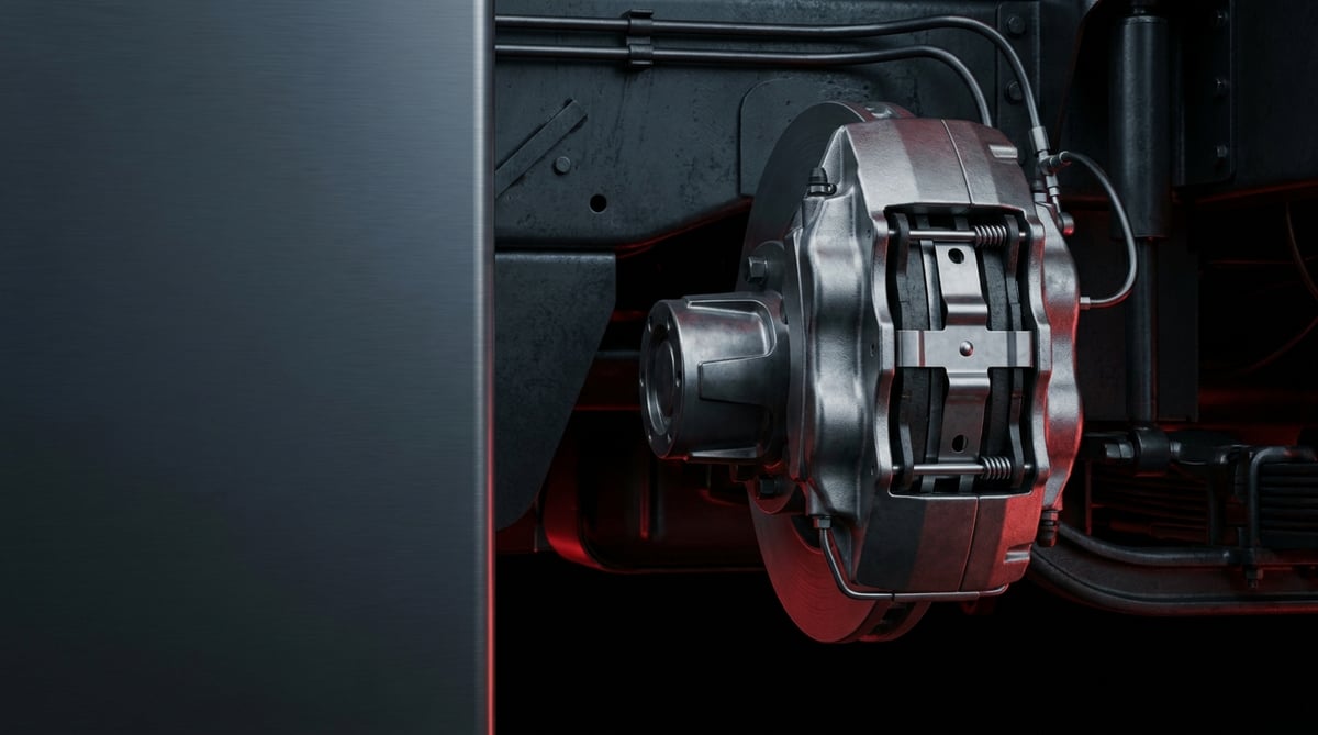
When a brake pad is changed on a disc-braked tractor unit, the first thing most technicians look at is pad thickness; yet the small kit that holds the pad in its carrier abutment matters just as much. On a caliper with a loose retainer bridge, a fatigued spring or a distorted pad plate, the pad no longer wears evenly, a grinding, chattering noise appears at the pedal and, worst of all, the two wheels on the same axle start braking differently. A large share of the vehicles that arrive at the workshop with "we changed the pads but the noise stayed" have no fault in the pad at all: the retainer kit was left out or reused in a worn condition. This guide explains, from a service point of view, what the caliper pad retainer and pad plate do, how their failures announce themselves, the correct diagnostic order, the discipline required during removal and refitting, and the maintenance habits that extend their life.
What Is a Caliper Pad Retainer & Pad Plate? Function and Operating Principle
The caliper pad retainer and pad plate are the mechanical elements that secure the pads in their abutment inside a heavy commercial vehicle air disc brake caliper and spread the force of the thrust element (tappet) evenly across the pad backing plate. The retainer bridge, spring and pin kit prevent the pad from moving in its abutment under the typical 8–8.5 bar service pressure of a 22.5 inch wheel group, while the pad plate prevents point loading from distorting the backing surface.
The same group of parts is known in the workshop and in catalogues under several names: pad retainer bridge, pad retaining spring, pad retaining pin, pad plate, thrust plate and, in some applications, caliper cover spring. They all belong to the same functional family: to locate the pad in the caliper abutment, to carry the vibration generated during braking and to let the pad release cleanly from the disc when the brake is applied and then released.
The operating principle is built on force transfer. Pressure arriving from the brake chamber is multiplied through the cam mechanism inside the caliper and passed to the thrust elements. The thrust element does not bear directly on the pad backing plate; the pad plate sits between them. By spreading a load that arrives at a single point across the back of the pad, the plate limits doming of the backing plate and the corner wear that follows from it. Meanwhile the retainer kit presses the pad radially and takes up the clearance in the abutment. When braking force is transferred from the pad into the caliper carrier, the retainer does not carry that force; its job is to prevent vibration and rattle and to release the pad on the return stroke.
Heavy commercial disc brakes use a sliding type caliper: thrust is applied only to the inner pad, and the caliper body slides on its guide pins so that the outer pad is also pressed against the disc. This architecture explains why the retainer kit is so critical. If the caliper slides, the pad moves too, at the micron level; once the retaining spring fatigues that movement grows to millimetres and the pad no longer separates fully from the disc when the brake is released. The result is a dragging pad, rising temperature and premature wear.
Brake approval framework and standards family
The caliper pad retainer and pad plate form part of an assembly that is assessed within the brake system approval of the vehicle. Heavy commercial vehicle braking performance is defined within the framework of ECE R13; for brake pads and pad kits supplied as replacement parts, the ECE R90 approval regime applies. For the characterisation of friction material, dynamometer test standards such as ISO 26867 are used as a reference. Although the retainer and the pad plate are not themselves the direct subject of these approvals, using a retainer that alters the geometry in which the pad kit was approved means the system departs from its defined operating condition. The applicable standard revision and the kit within which the part was approved must be verified from the relevant OE catalogue.
Components of the retainer kit
- Pad retainer bridge (bracket/spring bridge): The steel bridge that sits transversely across the caliper mouth and presses the pads into position.
- Retaining pin / guide pin: The element that connects the bridge to the caliper body, secured in most applications by a safety pin or a bolt.
- Pad retaining spring (leaf spring): The spring plate that bears on the back of the pad, takes up radial clearance and prevents rattle.
- Pad plate (thrust plate): The plate that sits between the thrust element and the back of the pad, spreading the load and limiting heat transfer.
- Safety clip / pin: The small but indispensable locking element that stops the bridge from working loose under vibration.
- Wear sensor seat and cable retainer: The parts that keep the cable on the pad routed correctly in sensor equipped applications.
Application differences: design varies with the caliper family
The design of the caliper pad retainer and pad plate depends far less on the make of the vehicle than on the brake caliper family built into it. The OE caliper families most often encountered in the field on heavy commercial vehicles originate from Knorr-Bremse and Wabco; even the front and rear axles of the same tractor unit may carry different caliper sizes and therefore different retainer geometry. The table below is a comparison intended to guide service planning; the binding match is made from the caliper type label and the OE number.
| Caliper family / application | Retainer type | Typical disc diameter | Service note |
|---|---|---|---|
| Heavy tractor unit and trailer, 22.5 inch wheel group (Knorr-Bremse type) | Transverse bridge + leaf spring + safety pin | Ø430–Ø440 mm | Bridge and spring renewed together with the pad set |
| Heavy tractor unit and bus (Wabco PAN/MAXX type) | Bridge + bolted fixing, integrated spring | Ø430–Ø440 mm | The fixing bolt may be single use |
| Urban distribution and midibus, 19.5 inch group | Short bridge + single spring | Ø370–Ø400 mm | Abutment clearance is tighter, pad plate thickness is critical |
| Bus rear axle, intensive stop-and-go duty | Bridge + reinforced spring | Ø430 mm class | Spring life is shorter because of thermal fatigue |
| Trailer / semi-trailer axle | Standard bridge + spring kit | Ø430 mm class | Corrosion and road salt dominate retainer wear |
How can a Caliper Pad Retainer & Pad Plate fault be identified?
Caliper pad retainer and pad plate faults rarely announce themselves directly; they are read indirectly from the pad and the disc. Noise, an irregular wear pattern and a temperature difference are the three most reliable indicators. The table below matches field symptoms with their probable causes and the method used to confirm them.
| Symptom | Probable cause | Check / verification |
|---|---|---|
| Metallic rattle from the wheel area on rough roads with the brake released | Retaining spring fatigued, bridge loose, pad moving in the abutment | Move the pad radially by hand with the vehicle on the ground; visually confirm that the bridge and safety pin are in place |
| Pad worn at an angle from the corner or from one side | Pad plate distorted or omitted, load not distributed evenly across the surface | Measure the thickness difference between the leading and trailing edge of the removed pad with a caliper gauge; check the pad plate surface on a flat plate |
| Marked temperature difference between the two wheels on the same axle | The pad on one side is not fully retracting, the retainer is causing binding | Compare hub and disc temperatures with an infrared thermometer after a test drive |
| Friction noise continues after the brake is released, disc has blued | Pad seized in the abutment; corrosion product has swollen the retainer surface | Check that the caliper slides freely on its guide pins; inspect the cleanliness of the abutment and pad plate seating surfaces |
| Safety pin or clip missing, bridge sitting on one side only | The locking element has worked out under vibration or was never fitted | Visual inspection; examine the pin for deformation |
| Crushing on the pad backing plate, deep imprint on the pad plate | Pad plate reused with an old kit, surface hardness lost | Measure pad plate thickness with a caliper gauge, compare the depth of the load imprint |
| Vibration at the brake pedal, judder felt through the steering | Irregular pad contact and the disc thickness variation that follows from it | Measure disc thickness variation (DTV) with a dial gauge around the circumference |
| Rust blistering on the retainer bridge and spring, thinning cross section | Corrosion from salt and moisture; particularly on trailer axles | Inspect the cross section after wire brushing; if blistering is present the part is renewed |
Visual inspection order: from the outside in
Diagnosis starts with the cheapest step. First the caliper mouth is cleaned; it is then confirmed visually that both ends of the bridge are fully seated, that the safety pin is in place and that the spring bears on the back of the pad. Next the pad is moved radially by hand; if there is perceptible free play, the retainer kit is not doing its job. Finally the leading and trailing edge thicknesses of the pad are compared — angled wear almost always points to a load distribution problem.
Verification by temperature
After a short test drive, the temperatures of the two wheels on the same axle are compared with an infrared thermometer. A dragging pad leaves a disc that is noticeably hotter than its neighbour. This method alone does not separate binding caused by the retainer from binding caused by the caliper, but it shows within a few minutes which wheel needs to come off. The most common mistake in the field is measuring a single wheel and drawing a conclusion from it; the measurement must always be comparative across the same axle.
Reading backwards from the removed part
When the pad set is removed, the retainer, the pad plate and the pad are assessed together. A deepened load imprint on the pad plate shows that this plate has run for at least one set too long. If the bridge is bent, the spring has taken a permanent set or the safety pin is deformed, the complete kit is renewed. If the seating surface on the pad backing plate has become polished, the pad has been moving in its abutment; in that case changing only the pad brings the problem back a few thousand kilometres later.
Standards and further reading
This subject is governed by the equipment rules for air-braked commercial vehicles. In the United States the federal air brake standard, FMVSS 121 (49 CFR 571.121) defines the reservoirs, protection and timing a compliant system must provide, and Europe applies the equivalent limits of UNECE Regulation No. 13. For further detail, see the on-road braking performance requirement in 49 CFR 393.52. Always confirm specific figures against the current regulation and the vehicle manufacturer service data.
Outside the United States the equivalent duties sit in national law. In the United Kingdom, regulation 18 of the Road Vehicles (Construction and Use) Regulations 1986 requires every part of the braking system to be maintained in good working order. In Canada, air brake systems fall under the Motor Vehicle Safety Regulations, which contain CMVSS 121.
How is a Caliper Pad Retainer & Pad Plate replaced? Step by step
- Secure the vehicle: Park on level ground, apply the parking brake, chock the wheels and make sure air pressure is stable. Choose the lifting points specified by the manufacturer and support the vehicle on stands.
- Remove the wheel, let it cool and take the initial measurements: After heavy duty the surface temperature of the disc and caliper is high; dismantling before cooling means both a burn risk and inaccurate measurement. Once the area has cooled, and before starting to dismantle, record pad thickness, disc thickness and the condition of the wear sensor — this data is the reference for the comparison after replacement.
- Clean the area: Free the caliper mouth, the bridge seating surfaces and the pad abutment from brake dust and corrosion product. A new retainer fitted into a dirty abutment runs in the wrong position from day one.
- Remove the locking element: Take out the safety pin or clip that holds the bridge. In most applications this element is single use; the removed pin is set aside and not reused.
- Release the bridge and spring under control: The bridge is under spring load. Press it down with a suitable tool and release it gradually, never letting it snap free. Set the removed bridge and spring aside, noting the position they came from.
- Remove the pads and pad plates: Lift the pads out of the abutment and carefully take the pad plates off the thrust elements. Always note which face of the plate was towards the pad; a plate fitted the wrong way round distributes the load incorrectly.
- Inspect the caliper and the thrust elements: Confirm that the caliper slides freely on its guide pins, that the boots are not torn and that the thrust element boots are intact. On a binding caliper, a new retainer kit will not solve the problem.
- Compare the new kit: Lay the new bridge, spring, pin and pad plates alongside the removed parts and compare length, thickness, bend and abutment geometry. Any difference must be verified before the part is fitted.
- Seat the pad plates and pads: Place the pad plates on the thrust elements the right way round and slide the pads into the abutment without forcing. If the pad does not enter easily by hand, the abutment is still dirty or the part is wrong; driving it in with a hammer is not an acceptable method.
- Torque the bridge and lock it: Bring the spring and bridge into position, tighten the fixing bolt or pin to the torque specified by the manufacturer, then fit a new safety pin or clip. A torque wrench is mandatory; a bridge tightened "by feel" either chokes the pad or works loose under vibration.
- Verify adjustment and clearance, then test: Check the automatic adjuster mechanism of the caliper according to the procedure, refit the wheel and tighten the nuts progressively. Then carry out a bedding-in drive with progressive braking at low speed and, after the test, compare disc temperatures across the axle.
What are the most common mistakes when replacing a Caliper Pad Retainer & Pad Plate?
- Assembling without cleaning the abutment: Corrosion product and brake dust cause the new pad to seize in the abutment and not retract fully.
- Fitting the pad plate reversed or omitting it: The load is not spread evenly across the surface; the pad starts wearing from the corner within a few thousand kilometres.
- Reusing the safety pin: A pin that has been bent once can work out under vibration the second time around.
- Forcing the pad into the abutment with a hammer: The backing plate and the abutment surface are deformed; the problem shows up not during assembly but on the first descent.
- Not using a torque wrench: Insufficient torque on the bridge fixing leads to loosening, excessive torque bends the bridge.
- Renewing the kit on one wheel only: Brake balance is established per axle; both sides of the same axle are dealt with together.
- Closing up without checking that the caliper slides freely: On a binding caliper even the best retainer kit does no more than mask the problem.
- Blowing brake dust out with compressed air: This is both a health risk and a way of carrying dust into the caliper boot and guide pin bore.
- Loading the vehicle without a bedding-in drive: New pads and a new retainer kit settle during the first progressive brake applications; if this step is skipped, performance in the first heavy braking event falls below expectation.
- Taking the wear sensor cable out of its route: A loose cable rubs against the disc or the bridge and breaks in a short time.
Caliper Pad Retainer & Pad Plate technical values and inspection points
The values given for the caliper pad retainer and pad plate are general reference ranges commonly encountered in heavy commercial vehicle air disc brake applications. The caliper family, axle position and equipment level shift these ranges; for exact data, the current OE service manual of the vehicle takes precedence.
| Parameter | Typical range (general reference) | Note |
|---|---|---|
| Service brake circuit operating pressure | 8–8.5 bar (116–123 psi) | Reservoir pressure is typically in the 10–12.5 bar band |
| Total thickness of a new pad (backing plate + friction material) | Approximately 28–32 mm | Varies with the caliper and disc family |
| Pad wear limit (friction material) | Approximately 2 mm above the backing plate | The limit value is taken from the manufacturer's manual |
| Disc thickness (new / wear limit) | Typically 45 mm / 37 mm in the Ø430 class | Varies with disc diameter; measured with a dial gauge |
| Disc thickness variation (DTV) tolerance | Generally below 0.05–0.10 mm | Pedal judder starts once it is exceeded |
| Radial clearance of the pad in the abutment (retainer fitted) | No perceptible movement | A pad that moves by hand indicates a fatigued spring |
| Pad plate thickness | Typically 2–5 mm | Renewed if crushed or deeply imprinted |
| Disc surface temperature (heavy descent) | Can reach the order of 400–700 °C | The main cause of thermal fatigue in the retaining spring |
| Disc temperature difference across the axle (after a test drive) | No marked difference | If a difference exists, binding is investigated |
| Fixing point | Typical torque band (general reference) | Application note |
|---|---|---|
| Pad retainer bridge fixing bolt | 25–45 Nm | In some applications the bolt is single use |
| Caliper guide pin cap bolt | 10–25 Nm | Boot integrity is checked at the same time |
| Caliper carrier bolts | High torque class, angle tightening common | Value and angle are taken only from the manual |
| Wheel nuts | Application specific high torque | Tightened progressively and crosswise, the manual governs |
- Is the retainer bridge fully seated at both ends, is the safety pin or clip in place?
- Does the pad move by hand in the abutment — if it does, the spring is fatigued.
- Is the pad plate the right way round, is there a deep load imprint or distortion on its surface?
- Is there corrosion blistering on the bridge and spring, or thinning of the cross section?
- Does the caliper slide freely on its guide pins, are the boots intact?
- Are the leading and trailing edge thicknesses of the pad close to each other?
- Is the wear sensor cable secured on its route and in its retainers?
- Are the disc temperatures across the axle close to each other after the test drive?
How is a Caliper Pad Retainer & Pad Plate maintained and its life extended?
The caliper pad retainer and pad plate have no calendar based replacement interval of their own; what determines their life is thermal load, corrosion and assembly discipline. In practice the right approach is to treat the retainer kit as part of the same service item as the pad. At every pad change the bridge, spring, safety pin and pad plate are assessed individually; where there is doubt, they are renewed. The cost of these elements stays low next to the cost of taking a wheel off a second time and standing the vehicle down.
- Assessment together with the pad: The retainer and pad plate are reviewed with every pad set; running the same kit through a second set should be the exception, not the rule.
- Abutment cleanliness: The pad abutment and the bridge seating surfaces are freed from corrosion product at every service. The use of oil and grease in the caliper area is limited to the points and products permitted by the manufacturer.
- Preserving caliper freedom: If the guide pin boots are torn, moisture and salt get inside; a binding caliper rapidly fatigues the retainer kit as well.
- Managing thermal load: Using the engine brake and retarder on long descents lowers the thermal load carried by the service brake and directly extends spring and pad plate life.
- Winter conditions and salt: On trailers and axles working on salted roads, retainer corrosion accelerates noticeably; a check at the end of winter is a good habit.
- Working per axle: Both sides of the same axle are renewed together; a one sided intervention upsets brake balance.
- Follow-up after the work: During the first few hundred kilometres after replacement, noise, temperature and pad position are checked again.
- Sensor and cable care: Keeping the wear sensor cable fixed in its retainers protects the life of both the sensor and the retainer.
In fleet operations the most efficient approach is to take the wheel off once and deal with the whole brake corner while it is off. Renewing the pad, retainer bridge, spring, safety pin and pad plate in the same service is markedly cheaper than bringing the vehicle back in a few months later because of rattle or angled wear. The most common reason for a repeat workshop visit in the field is the retainer kit being left in place during a pad change because it "still looks serviceable".
Related categories: Pad Holder · Brake Lining · Brake Caliper Pad Plate · Plate · Repair Kit
Main guide: Air Disc Brake Caliper: Faults, Replacement & Maintenance Guide
Tags
Frequently Asked Questions
- Is the pad retainer renewed at every pad change?
- It is not compulsory, but it is the recommended practice. The retainer bridge and spring are exposed to exactly the same thermal cycles as the pad and gradually lose spring force. If the spring has taken a permanent set, the bridge is bent, the cross section has thinned or corrosion blistering is present, the kit must be renewed. The safety pin and clip are single use in most applications.
- What does the pad plate do, can the brake work without it?
- The pad plate is the plate that spreads the force coming from the caliper thrust element across the pad backing plate and limits heat transfer. When it is missing or fitted the wrong way round, the load remains concentrated at a point; the pad wears from the corner, the backing plate domes and irregular contact forms on the disc. Where a pad plate is foreseen in the design, fitting it is mandatory — it is not an element that can be left out.
- Can the retainer be the cause of a rattle heard with the brake released?
- Yes; a metallic rattle heard on rough roads without the brake applied is the most typical symptom of a fatigued pad retaining spring. When the spring no longer takes up radial clearance, the pad moves in its abutment and the backing plate strikes the abutment at every impact. Verification is simple: with the vehicle secured and the wheel removed, the pad is moved radially by hand; if there is perceptible play, the kit is renewed.
- To what torque is the pad retainer bridge tightened?
- The bridge fixing bolt is tightened, as a general reference, to bands in the order of 25–45 Nm depending on the caliper family; in some applications the bolt is single use. Insufficient torque leads to loosening under vibration, excessive torque bends the bridge and chokes the pad. The exact value must be taken from the vehicle's current OE service manual and a torque wrench must always be used.
- Are the caliper pad retainer and the pad retaining spring the same thing?
- They are two different elements of the same kit. The retainer bridge is the carrier element that sits transversely across the caliper mouth and holds the spring in position; the spring is the flexible plate that bears on the back of the pad and takes up radial clearance. In some caliper families the two are produced as a single piece, in others they are ordered separately. When searching a catalogue, the caliper type and the OE number make this distinction clear.
- What happens if I fit the wrong retainer?
- A retainer with the wrong geometry, even if it looks "close enough" during assembly, either presses the pad too hard and prevents its return or does not press it enough and lets it move. In the first case the pad drags, disc temperature rises and premature wear begins; in the second, rattle and irregular wear appear. Both outcomes are unacceptable because they upset brake balance; the part must be verified against the caliper type.
- Under which standards are the pad retainer and pad plate assessed?
- Heavy commercial vehicle braking performance is defined within the framework of ECE R13; for brake pads and pad kits supplied as replacement parts, the ECE R90 approval regime applies. For the characterisation of friction material, dynamometer test standards such as ISO 26867 are used as a reference. Although the retainer and pad plate are not themselves the direct subject of these approvals, they are part of the geometry in which the pad kit was approved; the kit within which they are covered must be verified from the relevant OE catalogue.
- Is a bedding-in drive necessary after changing the retainer kit?
- It is necessary. New pads and a new retainer kit settle into the abutment and against the disc surface during the first progressive brake applications. Without a bedding-in drive carried out at low speed with intermittent, progressive braking, the expected friction coefficient may not be reached in the first heavy braking event. After the drive, disc temperatures across the axle should also be compared to confirm that there is no binding.
- How do I select the correct caliper pad retainer and pad plate?
- The vehicle model alone is not sufficient for the selection. The type label on the caliper body, the axle position (front/rear/trailer), the disc diameter and, where possible, the OE reference number on the removed part must be used together. Searching the VADEN catalogue can be done on the basis of this data: you can reach an application based list from the caliper type, or search the OE number of the old part directly and see the matching VADEN part number. Laying the new part alongside the removed one and comparing length, thickness and bend geometry before fitting is the safest final step.
- Is it enough to change the retainer on one wheel?
- It is not enough. Brake balance is established per axle; having a new retainer kit on one side of an axle and a fatigued one on the other makes the two wheels behave differently during braking. This causes both a pull under braking and premature wear of the pad on one side. Replacement must always be done per axle, with both sides treated together.
Related Articles

Caliper Tappet & Dust Boot: Function, Failure, Replacement
Caliper tappet and dust boot on truck air disc brakes: what happens when the boot tears, why tappets seize, and how to inspect, measure and replace them.
Caliper Cover, Gasket & Plate: Faults, Replacement, Care
How caliper cover, gasket and plate faults develop on truck air disc brakes, how to diagnose leaks, replace the group correctly and extend its life.
Brake Caliper Rubber Repair Kit: Failure & Replacement Guide
Brake caliper rubber repair kits explained: dust boots, o-rings, seals, pin bushings, failure signs, step-by-step replacement and the right grease to use.


