Rocker Arm & Shaft Set: Faults, Replacement and Maintenance
Learn how a heavy truck rocker arm and shaft set works, how to spot bushing wear, measure valve clearance and replace the assembly step by step.
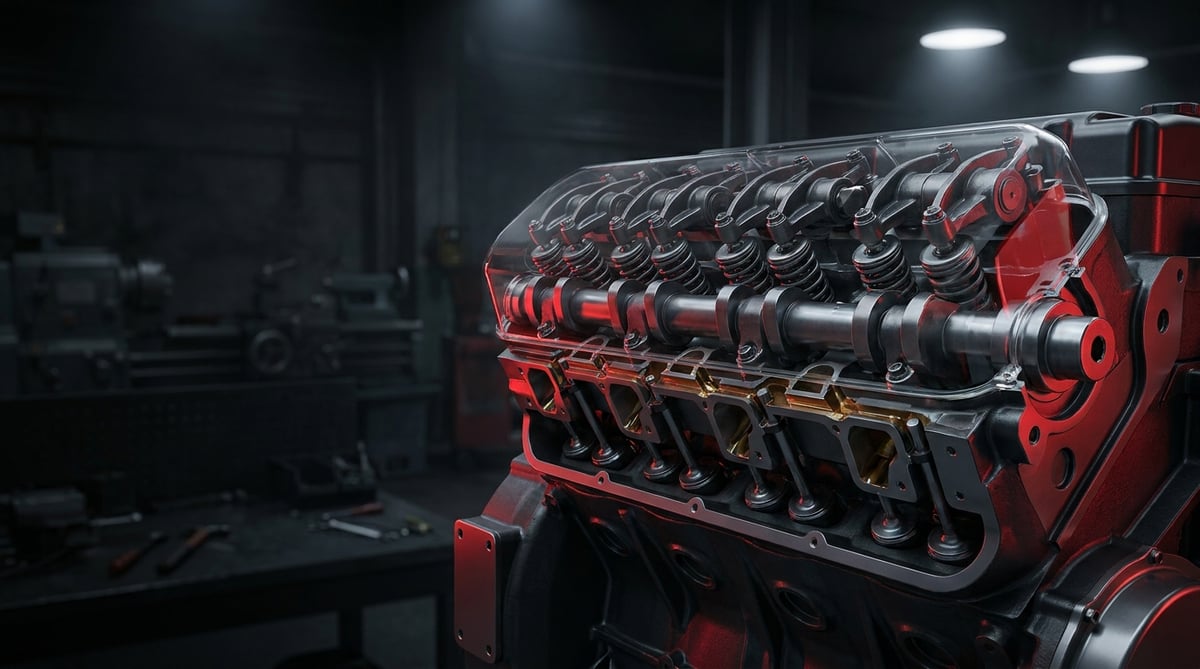
When the engine cover is opened on a heavy commercial vehicle, the rocker gear is the first mechanism that catches the eye, and it is also the area most often discussed in the field under the heading of "ticking noise". An engine that ticks when cold and goes quiet once warm, and an engine whose noise hardens as revs rise, point to two completely different faults in the same area. Going straight to valve clearance adjustment on the basis of noise alone is a common habit, but clearance adjustment usually corrects the symptom, not the cause. This guide explains what the assembly does, which symptom points to which component, the correct removal and tightening sequence, and the maintenance habits that determine service life, in the language of a service technician.
What Is a Rocker Arm & Shaft Set? Function and Operating Principle
A Rocker Arm & Shaft Set is the complete valve train assembly in heavy commercial vehicle engines that transfers motion from the camshaft to the valve or injector bridge, either through a push rod or by direct contact, working with a lever ratio typically between 1.4:1 and 1.8:1, and consisting of rocker arms, the shaft that carries them, bushings, adjusting screws and retaining elements. Valve clearance adjustment is also carried out through this assembly, generally within a band of 0.2–0.8 mm on heavy duty diesel engines.
The same group of parts is known by several names in the field and in catalogues: rocker arm, rocker lever, valve rocker, rocker shaft, rocker arm shaft, rocker gear and, in complete versions, shaft set. Regardless of the name used in the search, the selection criteria remain the same: engine code and OE reference number.
The operating principle is that of a lever. The cam on the camshaft pushes one end of the rocker arm upwards through the tappet and push rod; the arm pivots around its centre of rotation on the shaft and, with the adjusting screw or roller at the other end, presses on the valve stem or valve bridge to open the valve. The short stroke of the cam profile is converted into a greater opening distance on the valve side thanks to the lever ratio; when the cam base circle is reached, the spring closes the valve. Because this cycle is repeated hundreds of times per minute even at idle, the rocker gear is a group that works under continuous impact loading.
In heavy commercial diesels, the rocker gear does not only open valves. In unit injector architecture, a separate rocker arm presses the high pressure plunger of the injector; in engines equipped with an engine brake, an additional mechanism on the exhaust rocker performs the decompression function. For this reason, arms performing three or even four different tasks can sit side by side on the same shaft, and they cannot be fitted in place of one another.
How does lubrication work on the shaft?
A Rocker Arm & Shaft Set is connected to the engine's pressurised lubrication circuit. Oil enters the shaft carrier from the gallery in the cylinder head, then passes into the axial bore inside the shaft and is distributed to the bushing surface through radial holes aligned with each arm bearing. The practical conclusion is this: a lubrication problem in the rocker area almost never means "there is no oil"; it usually means that the hole is blocked, that the shaft has been fitted the wrong way round, or that hot idle oil pressure has dropped.
Difference between roller and pad (slipper) type arms
A Rocker Arm & Shaft Set is produced with two basic contact architectures. In pad type (slipper) arms, contact with the valve or bridge takes place through a hardened spherical surface with sliding friction; this is simple and durable but highly dependent on the oil film. In roller arms, contact is achieved by rolling on a needle bearing mounted roller; friction losses are low and more aggressive cam profiles are permitted, but the roller bearing is sensitive to dirty oil. One cannot be fitted in place of the other; arm height and cam profile are designed together.
Components and auxiliary elements
- Rocker arm (rocker lever): Forged steel or spheroidal graphite cast iron body; different geometries for intake, exhaust and injector.
- Rocker shaft: Hardened, hollow steel shaft; also acts as an oil distribution gallery.
- Bushing (bearing sleeve): Bronze or composite sleeve pressed into the arm body; wear begins here.
- Adjusting screw and lock nut: The element by which valve clearance is set.
- Roller and needle bearing: Cam or bridge contact in roller type arms.
- Shaft carriers (pedestals) and bolts: The elements securing the shaft to the head, tightened with an angle stage in most applications.
- Springs, spacer washers and circlips: Elements that maintain the axial position of the arms on the shaft.
- Valve bridge (crosshead) and guide pin: Distributes motion to two valves in multi valve heads.
| Engine family (application example) | Valve train architecture | Number of arms on the shaft (per cylinder) | Characteristic service note |
|---|---|---|---|
| Mercedes-Benz OM 457 / OM 470 / OM 471 | Overhead camshaft, valve + injector rocker | 2–3 (intake, exhaust, injector/engine brake) | The injector rocker works to a separate adjustment value |
| Volvo D11 / D13 | Overhead camshaft, exhaust arm with integrated engine brake | 3 (intake, exhaust, injector) | The engine brake mechanism sits on the exhaust arm |
| MAN D20 / D26 | Overhead camshaft, separate carrier per cylinder | 2–3 | Carrier bolts are mostly tightened with an angle stage |
| DAF MX-11 / MX-13 | Overhead camshaft, common rail | 2 (intake, exhaust) + engine brake equipment | Lever ratio and clearance values vary with the emission class |
| Scania DC13 | Overhead camshaft, unit injector or common rail | 2–3 | On unit injector versions the injector arm carries a high load |
| Iveco Cursor 9 / 11 / 13 | Overhead camshaft, roller type arm | 2 | The roller bearing is sensitive to oil cleanliness |
| Classic side camshaft heavy diesels | Push rod operated, arms in line on a common shaft | 2 | Push rod straightness is checked separately |
How do you recognise a Rocker Arm & Shaft Set fault?
Rocker Arm & Shaft Set faults almost always announce themselves first through noise and then show up in performance data. The most common misconception in the field is to attribute every ticking noise to valve clearance; in fact, clearance opening up on its own is usually the result of bushing, adjusting screw tip or bridge wear. The table below matches field symptoms with probable causes and verification methods.
| Symptom | Probable Cause | Check / Verification |
|---|---|---|
| Pronounced metallic ticking when cold, noise easing as the engine warms up | Valve clearance out of specification; adjusting screw lock nut loose | Feeler gauge measurement with the engine cold following the manufacturer's procedure; torque check of the lock nut |
| Knocking that hardens with rising revs and is not rhythmic | Excessive clearance between the arm bushing and the shaft | Feeling for play by moving the arm radially by hand; measurement with a dial gauge and checking the shaft diameter with a micrometer |
| Power loss on one cylinder, rough idle, pulsing sound at the exhaust | Adjusting screw tip or valve bridge worn; arm contact impaired | Comparison of clearance measurements between cylinders; inspection of the bridge and screw tip with a magnifier |
| Pitting, roughening or blue heat discolouration on the arm surface when the cover is opened | Oil film breakdown, blocked oil hole or low hot idle oil pressure | Checking the shaft oil holes for clear passage with compressed air; measuring oil pressure at hot idle |
| Reduced engine brake performance, knocking when the brake engages | Wear or adjustment drift on the exhaust arm carrying the engine brake mechanism | Checking the engine brake setting with its own separate procedure; observing free movement of the mechanism |
| Bright metallic swarf or bronze coloured particles in the oil sump | Bushing material or roller bearing has started to break up | Cutting open and inspecting the filter body while draining the oil; opening the cover and inspecting all arms |
| Clearance opening up again shortly after adjustment | Wear is ongoing; push rod seat or spherical seat in the arm has become hollowed | Re-measurement after a few hundred kilometres following adjustment; inspection of push rod ends |
| Oil leak in the area close to the shaft, dampness along the cover gasket line | Loosening of the shaft carrier bolts, non flatness of the cover | Checking carrier bolt torques; checking the cover surface with a straight edge and feeler gauge |
| Hard knocking in the injector rocker area (on unit injector engines) | Injector arm setting has drifted or the spherical seat in the arm is worn | Checking the injector arm setting with its own procedure; measuring the arm tip |
Clearance diagnosis with a feeler gauge
The first step in Rocker Arm & Shaft Set diagnosis is valve clearance measurement carried out on a cold engine and following the firing order sequence stated by the manufacturer. The diagnostic value lies less in the figure for a single cylinder than in the distribution between cylinders: if all have opened up by an equal amount, this is normal wear; if one arm stands out clearly, the bushing, screw or bridge of that arm is suspect. The feeler blade must enter parallel to the contact surface and pass with slight drag; a "forced fit" or "loose play" feel indicates a measurement error.
Measuring bushing and shaft clearance
The real wear pair on a Rocker Arm & Shaft Set is the arm bushing and the shaft. In field diagnosis, with the cover open, the arm is moved radially by hand; any perceptible movement already indicates that the limit has been exceeded. Precise assessment is made by measuring the shaft diameter with a micrometer and the bushing bore with an internal dial gauge and taking the difference. Local hollowing (a step) forming in the arm seating areas of the shaft shows up in measurement even when it is too small to see; for this reason, renewing only the arm and leaving a worn shaft in place is a frequent diagnostic error.
Verifying the lubrication path
If there is repeated wear in the Rocker Arm & Shaft Set area, diagnosis must be extended as far as the oil circuit. With the shaft removed, the axial and radial oil holes are checked with compressed air; carbon and oil sludge accumulate in these holes. On the engine, oil pressure measured at hot idle is decisive; borderline pressure shows itself first at the rocker gear, the most distant consumer. Finding that the true cause of worn arms is an extended oil change interval is one of the most frequently encountered situations in the field.
Further reading
For a plain-language technical overview of this subject, see the reference article on Wikipedia. Always confirm specific figures and procedures against the vehicle manufacturer service data.
How is a Rocker Arm & Shaft Set replaced? Step by step
- Secure the vehicle and let the engine cool: Apply the parking brake, chock the wheels, stop the engine and wait for it to cool. Disconnect the negative terminal of the battery. On applications requiring the cab to be tilted, always engage the tilt safety lock.
- Gain access and remove the cover: Remove the engine top cover, air pipes, cable ducts and, if necessary, the injector connectors, labelling them as you go. Loosen the rocker cover bolts progressively from the outside inwards, and once the cover is off, wipe the area with a clean cloth; oil sludge falsifies both measurement and assembly. The cover gasket is single use in most applications.
- Take measurements before dismantling: Record the existing valve clearances cylinder by cylinder. This record is the quickest way to establish whether the fault lies in a single arm or in general wear, and it serves as a reference for comparison after assembly.
- Loosen the shaft carrier bolts progressively: Loosen the bolts in several passes, symmetrically from the inside outwards, rather than all at once. Because the valve springs push the shaft upwards, rapid loosening at a single point can bend the shaft or crack the carrier.
- Remove the shaft assembly as a unit and mark it: The shaft, arms and carriers should be removed together where possible; each arm must be marked with the cylinder number and intake/exhaust information and laid out in order on a tray. If their positions are mixed up, bedded in contact surfaces will not match.
- Check the push rods and bridges: Check push rods for straightness by rolling them on a flat surface and inspect their end spheres visually. Look for pitting on the valve bridges and wear on the guide pin; if the rocker is renewed and a worn bridge is left in place, the noise will return before long.
- Assess the removed assembly by measurement: Measure the shaft diameter in the arm seating areas and the bushing bore with a dial gauge. If there is pitting on the arm contact surface, hollowing at the adjusting screw tip, stiffness in roller rotation or heat discolouration, the part is renewed; if the wear affects more than one arm, replacement as a complete set is the right decision.
- Prepare the new set with lubrication: Verify that the oil holes in the new shaft are clear and free of burrs; apply clean engine oil or the assembly compound recommended by the manufacturer to the shaft, bushings and contact surfaces. Dry assembly leaves permanent scoring in the first few seconds.
- Fit the shaft paying attention to its orientation: The oil holes and the locating dowel permit only one correct orientation; a shaft fitted the wrong way round discharges oil into the cover instead of to the bushings. Visually confirm that the push rods are seated in their sockets and that the arms are centred on the bridge.
- Tighten in the correct sequence and to the correct torque: Tighten the carrier bolts in the sequence given by the manufacturer, from the inside outwards and in at least two stages; on many heavy commercial engines the final stage is angle tightening (torque + degrees) and these bolts may be single use. The accuracy and calibration requirements for torque tools are defined in the ISO 6789 family of standards; check that the calibration of the wrench you use is still valid.
- Adjust the valve clearance and close up: Set the clearances on a cold engine, following the manufacturer's firing order sequence; while tightening the lock nut, verify with the feeler gauge that the setting has not shifted. Fit the cover with a new gasket, start the engine and monitor noise and oil pressure at idle, then check the values again after a short test drive.
What are the most common mistakes when replacing a Rocker Arm & Shaft Set?
- Mixing up the positions of the arms: When a bedded in contact surface meets a different valve, accelerated wear begins; labelling must not be neglected during removal.
- Fitting the intake and exhaust arms in place of one another: Although they look similar from the outside, the lever ratio and contact geometry are different; the adjustment range will not be met.
- Tightening the carrier bolts in a single pass: Asymmetric tightening against the resistance of the valve springs bends the shaft and creates a risk of cracking in the carrier.
- Skipping the angle tightening procedure: Bolts tightened on the basis of "roughly the same torque" work loose over time; reusing a single use bolt carries the same risk.
- Dry or reversed assembly: A shaft run without lubrication is scored in the first few seconds; on a shaft fitted the wrong way round, the oil holes miss their target.
- Ignoring the bridge, push rod and valve tip: The wear chain is not limited to the rocker alone; the noise returns before long.
- Tightening the lock nut without holding the adjusting screw: The screw turns, the setting drifts and the measurement is wasted.
- Replacing parts alone without investigating the root cause: If low oil pressure or an extended oil change interval continues, the new set will last exactly as long as the old one.
Rocker Arm & Shaft Set technical values and inspection points
The values below for a Rocker Arm & Shaft Set are general reference ranges frequently encountered on heavy commercial diesel engines. Engine family, emission class, engine brake equipment and year of manufacture change these ranges significantly; for exact data, the current service manual specific to the engine code is authoritative. Arm body and shaft material generally falls into the class of quenched and tempered steels (EN 10083 family of standards) or high strength spheroidal graphite cast iron (EN 1563 family of standards), while the roughness of contact surfaces is specified using ISO 4287 definitions. These standard equivalents describe the material class and do not commit any particular part — exact material and surface data must be verified from the relevant OE catalogue.
| Parameter | Typical range (general reference) | Note |
|---|---|---|
| Valve clearance — intake (cold engine) | 0.20–0.50 mm | Specific to the engine code; measurement follows the firing order sequence |
| Valve clearance — exhaust (cold engine) | 0.40–0.80 mm | The exhaust side is larger because of thermal expansion |
| Injector rocker setting value (unit injector engines) | Separate procedure; generally based on preload or stroke | Must not be confused with valve clearance |
| Rocker ratio | Approximately 1.4:1 – 1.8:1 | Designed together with the cam profile; cannot be changed |
| Arm bushing to shaft radial clearance (new) | Approximately 0.02–0.08 mm | The service limit is usually appreciably above this; take it from the manual |
| Acceptance of local wear (step) on the shaft | A measurable step is not acceptable | If there is a step, the shaft is renewed |
| Engine oil pressure at hot idle | Approximately 1.0–2.5 bar (15–36 psi) | If it falls below, the rocker gear is the first area affected |
| Engine oil pressure at rated speed | Approximately 3.0–5.5 bar (44–80 psi) | Depends on oil viscosity and temperature |
| Operating temperature under the rocker cover | Approximately 90–130 °C | Determines the breakdown limit of the oil film |
| Adjusting screw tip / bridge contact surface | Pitting and polishing are not acceptable | If visible hollowing is present, the part is renewed |
| Connection point | Typical torque band (general reference) | Application note |
|---|---|---|
| Shaft carrier (rocker pedestal) bolt | 40–90 Nm + angle stage | Tightened progressively and symmetrically; single use in many applications |
| Adjusting screw lock nut | 20–50 Nm | Tightened while holding the screw; clearance is then verified again |
| Rocker cover bolt | 8–25 Nm | From the inside outwards, progressively; overtightening crushes the gasket |
| Valve bridge guide pin / retaining element | Application specific | Some engines have a separate adjustment procedure |
- Are the valve clearances balanced between cylinders, or does one arm stand out?
- Is there perceptible radial play when the arms are moved by hand on the shaft?
- Is there a step, scoring or heat discolouration on the shaft surface in the arm seating areas?
- Are the axial and radial oil holes of the shaft clear, or is there carbon build up?
- Are the adjusting screw tip, roller and valve bridge contact surfaces pitted?
- Are the push rods straight and are their end spheres sound?
- Are there signs of loosening, stretching or thread damage on the carrier bolts?
- Is oil pressure at hot idle within the expected band, and are there bronze coloured or bright metallic particles in the oil filter and sump?
How is a Rocker Arm & Shaft Set maintained and its service life extended?
There is no fixed replacement interval defined for a Rocker Arm & Shaft Set; three things determine its service life: oil cleanliness, continuity of oil pressure, and carrying out valve adjustment at the specified intervals. A properly maintained set can run trouble free for the main service life of the engine. By contrast, extended oil change intervals and missed valve adjustment accelerate wear: as clearance grows the impact increases, as the impact increases the bushing wears faster, and the process enters a self reinforcing cycle.
- Oil and oil filter discipline: The rocker gear is one of the most distant consumers on the oil circuit; it is the first to show the effect of oil that has become contaminated and lost viscosity. The manufacturer's interval must not be exceeded.
- Correct viscosity and OE approved oil: Departing from the specification on the engine manufacturer's approval list can lead to breakdown of the oil film at hot idle.
- Carrying out valve adjustment at the specified intervals: Adjustment is not merely a noise removal operation but preventive maintenance. Correct clearance limits the impact loading and extends the life of both the arm and the valve.
- Recording the measurements during adjustment: Recording the values measured at every service shows the wear trend early; an arm that deviates suddenly is noticed before it fails.
- Monitoring oil pressure: Pressure dropping at hot idle is a warning that should be acted on before any noise is heard in the rocker area.
- Carrying out a full inspection while the cover is off: If the cover has already been removed, the bridges, push rods and gasket surface should also be inspected; opening the cover a second time means repeating the entire labour.
- Not loading the engine during cold starts: High revs before the oil has warmed up increase impact loading at the moment when the film is at its weakest.
In fleet operations, the most efficient approach is to plan the rocker gear as a working assembly rather than as individual parts. Assessing the arm, shaft, bushing, adjusting screw and, if necessary, the valve bridges together when the cover is opened costs far less than bringing the vehicle back into the workshop a second time a few months later.
Related categories: Rocker Swing Arm · Arm and Shaft Set · Rocker Arm
Main guide: What Is a Crankshaft? Function, Failure Symptoms and Maintenance
Tags
Frequently Asked Questions
- Can the vehicle be driven with rocker arm ticking?
- It can be driven over a short distance and at low load, but continuing on the road without understanding the cause of the noise is not advisable. While a simple clearance deviation is corrected by adjustment, advanced bushing wear or a broken adjusting screw can cause far heavier damage, including valve to piston contact. When ticking is noticed, the cover should be opened and the valve clearance measured as soon as possible.
- Can the rocker shaft and the rocker arm be replaced separately?
- Technically they can be sold separately, but they must be assessed together. The arm bushing and the shaft form a working pair; when a new arm is fitted to a worn shaft, the contact surface is loaded at a single point and the clearance returns before long. If there is a measurable step or a reduction in diameter on the shaft, both must be renewed together. For this reason, a complete shaft set is usually preferred in heavy commercial applications.
- How often should valve adjustment be carried out?
- The interval varies according to the engine manufacturer, the duty profile and the emission class; on heavy commercial diesels it is generally planned at specific mileage or engine operating hour intervals, and the exact figure is taken from the vehicle's service schedule. On demanding profiles such as urban stop start work, heavy loads or intensive engine brake use, it is particularly important not to miss the adjustment; adjustment is not just noise removal but preventive maintenance that limits impact loading.
- What is the most common cause of rocker arm wear?
- The root cause most frequently encountered in the field is oil related: extended oil change intervals, unsuitable viscosity, a blocked shaft oil hole or low oil pressure at hot idle. Missed valve adjustment comes second; growing clearance increases the impact, the impact wears the bushing faster, and the process accelerates itself. These two root causes must be eliminated before the part is renewed.
- Are the intake and exhaust rocker arms the same part?
- No. Even though they look similar from the outside, the intake and exhaust arms have different lever ratios, different contact geometry and usually different part numbers. The exhaust side works at higher temperature and load, and on engines equipped with an engine brake the additional mechanism is also carried on this arm. On arms fitted in each other's positions, the valve clearance adjustment range will not be met.
- Is valve adjustment essential after rocker arm replacement?
- Yes, without exception. A new arm, new bushing and new adjusting screw give a different contact height from the removed part; on an engine run without adjustment the clearance either drops to zero and the valve does not close fully, or remains excessively open and the engine runs with impact. Adjustment must be carried out on a cold engine following the manufacturer's firing order sequence, and the measurement must be repeated after the lock nut is tightened.
- How is rocker arm noise distinguished from injector noise?
- The distinction is made by rev behaviour and location. Clearance noise originating from the rocker is a metallic ticking that is pronounced when cold and eases as the engine warms up, and when listened to through the cover it is concentrated at the point where the arm is located. On unit injector engines, the noise from the injector rocker is harder and deeper and becomes more pronounced with rising revs. For a definite distinction, point listening with a stethoscope is required, followed by measuring both settings with their own procedures.
- Why do rocker shaft oil holes become blocked?
- The main cause of blockage is oxidation of the oil into sludge together with carbon build up; extended oil change intervals, frequent short distance use and combustion faults producing excessive carbon accelerate this process. As the hole narrows, the oil flow reaching the bushing falls, the film breaks down and wear begins. When the shaft is removed, the axial and radial holes must always be cleaned and checked for clear passage with compressed air.
- How do I choose the correct rocker arm / shaft set?
- The vehicle model alone is not sufficient. The engine code, year of manufacture, emission class, engine brake equipment and, if possible, the OE reference number on the old part must be used together. Searching in the VADEN catalogue can be done on the basis of these two data points: with the engine code (for example OM 471, D13 or MX-13) you can reach an application based list, or by searching directly for the OE number on the old arm or shaft you can see the matching VADEN part number. Before ordering, also confirm the arm type (roller / pad) and the intake–exhaust distinction.
- In which sequence are the rocker cover bolts tightened?
- Rocker cover bolts are always tightened from the centre outwards and in stages; the final torque is never reached in a single pass. As a general reference, bands in the order of 8–25 Nm are seen, and overtightening crushes the gasket and causes leakage. The shaft carrier bolts are different: on most heavy commercial engines they are tightened with torque plus an angle stage, and in some applications they are single use. For the exact sequence and values, the vehicle manufacturer's service manual specific to the engine code must be taken as the basis.
Related Articles

Oil Filter Cap and Housing: Leaks, Cracks and Seal Replacement
Truck engine oil filter cap and housing: why plastic caps crack, O-ring leak causes, bypass valve faults, and correct torque and seal replacement steps.
Piston Rings: Oil Consumption, Compression Loss and Replacement
Ring-related oil consumption and compression loss in truck diesel engines: how rings seal, blow-by and leak-down tests, ring gap and replacement.
Intake Manifold and Intake Pipe: Faults, Diagnosis, Repair
How the intake manifold and charge air pipe work on truck diesel engines, how to spot boost leaks, run a pressure test and fit them leak free.


