Compressor Connection Hardware: Faults, Replacement, Care
How truck air compressor adapters, bolts, plugs and hoses fail, how to diagnose leaks and blockages, replace them correctly and extend service life.
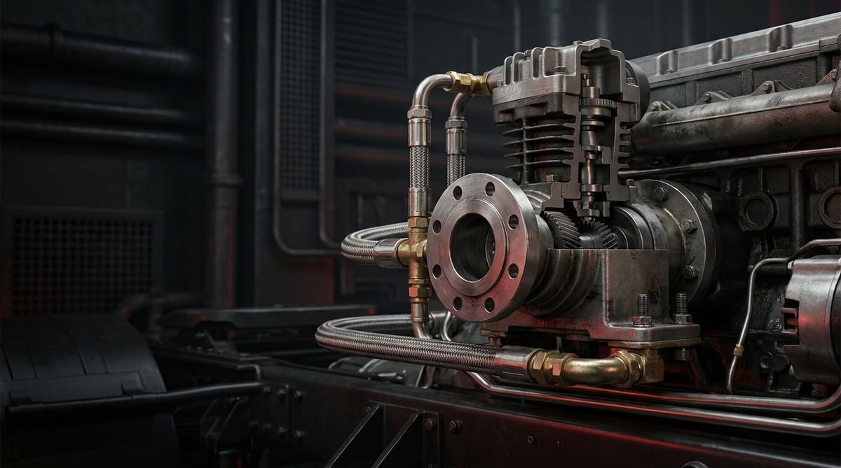
When a vehicle comes back to the workshop two weeks after an air brake compressor replacement, the culprit is usually not the compressor itself. The most common scenario in the field is this: the compressor is new, but the adapter on the discharge port is old, the mounting bolt has been over-tightened once too often, the oil return hose has hardened, and the sealing washer under the plug fitted to an unused port has been used a second time. The hardware around the compressor is just as critical as the body itself; the air, oil and coolant circuits all pass through these small components. This guide explains the function of compressor connection hardware, its failure symptoms, the correct diagnostic sequence, the discipline required during removal and refitting, and the maintenance habits that extend its service life, all from a workshop foreman's point of view.
What Is Compressor Connection Hardware: Adapter/Bolt/Plug/Hose? Function and Operating Principle
Compressor connection hardware is the group of ancillary components made up of adapters, bolts, plugs and hoses that connect the air brake compressor to the engine block, the lubrication circuit, the coolant line and the air supply line. The components of this group typically have to carry 8–12.5 bar system pressure, short-term temperatures of 150–200 °C at the discharge port and engine vibration all at the same time.
The compressor is not a stand-alone unit on a heavy commercial vehicle. It is driven by the engine, shares the engine's oil and usually its coolant, sends the compressed air it produces to the air dryer, and receives its unloading signal from the governor. In other words, it is connected to four separate circuits at once: air, oil, water and mechanical mounting. Each of these four circuits has its own adapter, its own set of bolts, its own sealing element and its own hose. That is exactly why a single "compressor parts" heading in the catalogue contains hundreds of individual items.
The operating principle follows the logic of a chain, and every link in that chain carries a different load. The intake side delivers air coming from the air filter or the turbocharger supply line to the compressor; pressure here is low, but the risk of foreign matter is high. The discharge side carries the hot air leaving compression to the air dryer; here both pressure and temperature peak, and metal pipe or high-temperature reinforced hose is generally used. The oil supply line carries pressurised oil from the engine oil gallery to the crankshaft bearing; because of its small cross-section it is the line most prone to blockage. The oil return line, in contrast, works by gravity; it is unpressurised, but it does not forgive any reduction in cross-section. The coolant line transfers heat from the cylinder head to the engine circuit and, in most heavy commercial applications, is the component that actually keeps compressor temperature within an acceptable band.
The role of adapters and fittings
Adapters are transition components that convert the port thread on the compressor body to the thread of the line. In heavy commercial applications you generally encounter metric parallel threaded ports with O-ring sealing (the ISO 6149 family), metric tapered threads, or cutting-ring tube fitting systems (the DIN 2353 / ISO 8434-1 family). It is common for different circuits on the same body to use different thread systems. The applicable standard and the sealing method vary with the compressor family; exact data must be verified from the OE catalogue for the part. The most expensive mistake made in the field is assuming that an adapter whose thread engages therefore "fits": a parallel thread will enter a tapered seat and even turn a few times, but the sealing face will never seat.
Bolts, plugs and sealing elements
Compressor mounting bolts do not merely hold the part in place; cover and flange bolts also distribute the clamping load on the gasket. That is why the tightening sequence and torque are as important as the value itself. Plugs (blanking plugs) close off unused ports; they become essential in applications where the water circuit is not connected, or in installations where ports are swapped for a different mounting orientation. Banjo bolts and the copper or aluminium washers beneath them are single-use items: once crushed, they will leak on a second installation.
Hoses and pipework
Three different hose families are used around the compressor. The discharge line is a temperature- and pressure-resistant braided metal reinforced hose or a steel pipe. The oil supply and return lines use oil-resistant reinforced hose or rigid pipe. The coolant lines belong to the classic EPDM-based radiator hose family. The polyamide (PA) tubing widely used in the vehicle's air supply lines corresponds to air brake line standards such as DIN 74324 / SAE J844. The critical distinction is this: polyamide air tubing is never connected directly after the compressor discharge port without cooling. The temperature at the discharge outlet is above the service temperature of plastic tubing; for this reason a certain length of metal pipe or high-temperature hose follows the outlet.
The most frequently encountered items of compressor connection hardware, both in the catalogue and in the field, are the following:
- Discharge (outlet) adapter and fitting: connects the compressor outlet to the air dryer line and sees the highest thermal load.
- Intake adapter / flange: the connection to the air filter or turbocharger supply line, always considered together with its gasket.
- Oil supply banjo bolt and washers: narrow internal drillings, sensitive to blockage; washers are renewed at every removal.
- Oil return adapter and hose: works without pressure; any reduction in cross-section turns into a crankcase pressure problem.
- Coolant adapter and hose: transfers cylinder head heat to the engine circuit.
- Blanking plug: closes unused ports, sealing with an O-ring or a washer.
- Body / flange mounting bolts: distribute gasket load; the tightening sequence is defined.
- Unloader / governor signal line fitting: carries the small-diameter control line.
- Gasket and O-ring set: single-use items for flange, cover and port sealing.
| Circuit | Typical connection component | Operating range (general reference) | Characteristic service note |
|---|---|---|---|
| Air discharge (outlet) | Metal adapter, steel pipe or high-temperature reinforced hose | 8–12.5 bar · short-term 150–200 °C at the outlet | Plastic tubing is not connected directly; check for carbon build-up |
| Air intake | Flange, adapter, gasket, clamped hose | Atmospheric, or limited boost pressure on turbocharged supply | Ingress of foreign matter is the biggest risk; gasket is renewed |
| Oil supply | Banjo bolt, sealing washer, small-bore hose/pipe | In the order of engine oil pressure, typically 2–6 bar | If the narrow drilling blocks, bearing damage develops quickly |
| Oil return | Adapter, large-bore hose or rigid pipe | Unpressurised, gravity flow | Reduced cross-section and adverse gradient are not acceptable |
| Coolant | Adapter, EPDM hose, clamp, blanking plug where required | Engine circuit pressure, typically 1–2 bar · 80–100 °C | If the water connection is deleted, the port must be plugged |
| Mechanical mounting | Flange bolts, gear/belt drive connection components | Engine vibration and drive torque | Sequence and torque are defined; a torque wrench is mandatory |
How do you recognise a compressor connection hardware fault: adapter/bolt/plug/hose?
Compressor connection hardware faults almost always fall into three groups: leaking, blocking and loosening. An air leak lengthens the pressure build-up time, an oil leak leaves traces in the engine bay, and a blocked oil line destroys the compressor from the inside without giving any external sign at all. The table below matches field symptoms with probable causes and with the method used to confirm them.
| Symptom | Probable cause | Check / verification |
|---|---|---|
| Air pressure builds slowly, compressor runs almost continuously | Air leak at the discharge line adapter or fitting | Soap solution test with the system pressurised; measuring pressure build-up time with a gauge |
| Oil traces around the compressor, running marks on the block | Crushed oil supply banjo washer, hardened return hose or loose clamp | Clean the area and watch the direction of wetting with the engine running; check hose end and clamp |
| Wet coolant traces in the engine bay, dropping level | Water adapter or blanking plug leaking, hose end aged | Visual inspection with the engine cold; system pressure test to locate the leak point |
| Compressor overheating, carbon/soot build-up at the outlet | Restriction in the coolant line or an incorrectly plugged water port; restriction in the discharge line | Comparing hose temperatures by hand; removing the discharge pipe and inspecting its internal bore |
| Excessive oil coming from the air dryer and the reservoirs | Restriction in the oil return line, crushed hose or adverse gradient in the routing | Removing the return line and checking for free flow; verifying line gradient and routing |
| Abnormal noise from the compressor, bearing damage within a short time | Blockage in the oil supply line, wrong banjo bolt (drillings misaligned) | Removing the supply line and verifying pressurised oil delivery; comparing the bolt drillings |
| Blowing sound from the flange area, soot traces along the gasket line | Mounting bolts loose or tightened in the wrong sequence, gasket crushed | Check tightening with a torque wrench; removing and inspecting the gasket line |
| Pressure drop persists although no leak can be found | Missing or loose plug on an unused port, or a leaking unloader signal line fitting | Isolating circuit by circuit and following the pressure drop; verifying every port one by one |
Where is the leak: soap test and circuit isolation
The fastest way to find an air leak is still the foam test with soapy water; however, because foam dries quickly on a hot discharge line, the test should be carried out with the system pressurised and the engine cold. If the leak can be heard but the point cannot be located, isolate the circuits: disconnecting the compressor outlet from the air dryer and blanking it separates, in a single step, whether the leak is on the compressor side or further downstream.
Measuring pressure build-up time
Charging performance is the most objective indicator of the health of the connection hardware. If the time taken for an emptied system to reach the specified working pressure is clearly above the limit defined in the vehicle service manual, first a leak and then a restriction in the discharge line should be investigated. On heavy commercial vehicles, the supply and performance requirements of the brake system are defined within the scope of ECE R13; for measurement and acceptance limits, the vehicle's own service documentation is authoritative.
Verifying the oil line
Diagnosis of the oil supply line is not carried out by eye but by removal. When the supply connection is disconnected and the engine is cranked briefly, steady, pressurised oil should come from the line. If it does not, the banjo bolt, the adapter drilling or the line itself is blocked. On the return side the test is even simpler: once the hose is removed, it must be possible to blow air freely through it. The most common mistake in the field is a return line crushed under a clamp, with the fault written off against the compressor piston rings.
Standards and further reading
This subject is governed by the equipment rules for air-braked commercial vehicles. In the United States the federal air brake standard, FMVSS 121 (49 CFR 571.121) defines the reservoirs, protection and timing a compliant system must provide, and Europe applies the equivalent limits of UNECE Regulation No. 13. For further detail, see the illustrated reference guide at airbrakecompressor.com. Always confirm specific figures against the current regulation and the vehicle manufacturer service data.
Readers outside the United States should work from their own national framework: in the United Kingdom the braking system must be maintained under regulation 18 of the Road Vehicles (Construction and Use) Regulations 1986, and in India the governing rules are published by the Ministry of Road Transport and Highways.
How is compressor connection hardware replaced: adapter/bolt/plug/hose? Step by step
- Secure the vehicle: Stop the engine, apply the parking brake, chock the wheels and disconnect the battery isolator or the negative terminal. If the cab has to be tilted, lock the tilt safety catch.
- Exhaust the air system: Open the drain valves on all air reservoirs to make the system completely unpressurised. Do not open any fitting before you have confirmed a zero reading on the gauge.
- Prepare the coolant circuit: If the water connection is to be touched, drain the circuit into a suitable container once the engine has cooled. Do not pour the antifreeze mixture onto the ground; follow the waste disposal procedure.
- Clean the area: Use compressed air and a clean cloth to remove dust, grit and oil from around the adapter, banjo and flange to be removed. A single particle entering the air or oil circuit will quickly turn into bearing or valve damage.
- Mark and disconnect the lines: Before removal, mark or photograph the hose routings and fitting orientations. Open the fittings with a correctly sized open-end or flare-nut spanner while holding the counter nut; do not force the pipe by twisting it.
- Cap open ports immediately: Cap the end of every disconnected line and every opened port with a clean plug or cover. An oil port left open is the shortest route for dirt to enter the system.
- Inspect the removed parts: Examine the adapter sealing face, the thread lengths, the banjo bolt drillings, the internal bore of the hose and the gasket imprints. If you see crushing, an oval face, corrosion or carbon build-up, check the neighbouring components as well; a fault rarely involves a single part.
- Compare the new part with the old one: Place the new adapter, plug or hose next to the removed part; thread diameter and pitch, thread form (parallel/tapered), sealing method (O-ring/washer/tapered), length and bend geometry must match exactly. If they do not, the part is wrong; do not force it.
- Always renew the sealing elements: Banjo washers, O-rings, flange gaskets and, where applicable, single-use bolts are replaced with new items. Refitting an old washer because it "looks clean" is the most frequent cause of repeat work.
- Fit loosely first, then torque in the correct sequence: First turn all connections a few threads by hand so that the line settles into its natural position. Tighten flange and cover bolts with a torque wrench in the sequence defined by the manufacturer, crosswise and in stages. Secure the fittings and banjo connections last, at their own torque values. Tighten clamps and brackets only after confirming that the line sits without stress.
- Verify hose routing and clearances: No hose may touch the exhaust, the turbocharger or any moving part, and none may chafe against a sharp edge. Respect the minimum bend radius of the discharge line; a pinched or kinked hose narrows internally long before it leaks.
- Refill, start and test: Refill and bleed the coolant circuit, start the engine and wait until the air system builds pressure. Check all connections for leaks with soapy water and observe the area for oil seepage after wiping it dry. Repeat the check after a test drive, once the engine is fully warm; some leaks appear only after a thermal cycle.
What are the most common mistakes when replacing compressor connection hardware: adapter/bolt/plug/hose?
- Confusing parallel and tapered threads: Both will turn a few times, but only one will seal. The thread form must be verified with a caliper and a thread gauge.
- Reusing single-use washers: Copper and aluminium washers take their shape by being crushed once; on a second installation they leak.
- Fitting the wrong banjo bolt: A bolt whose thread engages but whose internal drillings sit in a different position can cut off oil flow; the result is bearing damage within a short time.
- Routing the oil return line with a reduced bore or an adverse gradient: The return works by gravity; a narrowing or rising route causes oil to collect in the compressor and to be carried into the air system.
- Connecting plastic tubing directly to the discharge outlet: The outlet temperature is above the service temperature of polyamide tubing; the tube softens, deforms and eventually splits.
- Leaving an unused port open or fitting an unsuitable plug: In installations where the water circuit is deleted, a blanking plug of the correct size and sealing type must be used.
- Tightening flange bolts in a random sequence: Gasket load is distributed unevenly and the joint starts blowing during the first thermal cycles.
- Relying on "feel" instead of a torque wrench: On compressors with aluminium bodies the torque tolerance is narrow; under-tightening leaks, over-tightening destroys the thread.
- Replacing the compressor but leaving the old hardware in place: Hoses, washers and gaskets of the same age and thermal history become the weak link that determines the life of the new compressor.
- Not cleaning the area before removal: Dirt around the fitting falls straight into the air or oil circuit the moment the joint is opened.
Compressor connection hardware technical values and inspection points: adapter/bolt/plug/hose
Compressor connection hardware values given below are general reference ranges commonly encountered on heavy commercial vehicle air brake systems. The compressor family, engine code, specification level and year of manufacture all shift these ranges; for exact data always consult the vehicle manufacturer's current service manual.
| Parameter | Typical range (general reference) | Note |
|---|---|---|
| System working pressure (governor cut-out) | 8–12.5 bar (116–181 psi) | Varies with vehicle class; the exact value comes from the manual |
| Discharge outlet air temperature | Short-term 150–200 °C under load | Plastic air tubing is not connected directly to this area |
| Oil supply pressure | In the order of engine oil pressure, typically 2–6 bar | Assessed separately at idle and at operating speed |
| Coolant circuit temperature | 80–100 °C, circuit pressure typically 1–2 bar | Transfers heat from the compressor body to the engine circuit |
| Discharge line pipe/hose internal diameter | Commonly in the Ø10–Ø16 mm band | Any restriction raises outlet temperature and carbon build-up |
| Oil return line internal diameter | Clearly larger than the supply line | Free flow is essential; not reduced, not sharply bent |
| Leak test acceptance criterion | Pressure drop must stay within the limit over the specified period | Limit values are vehicle-specific and taken from the service manual |
| Common port thread sizes | M12x1.5 · M14x1.5 · M16x1.5 · M22x1.5 band | The same pitch may have a different thread form; verify by OE number |
| Connection point | Typical torque band (general reference) | Application note |
|---|---|---|
| Cover / flange bolt M8 | 20–30 Nm | Crosswise, staged tightening sequence is mandatory |
| Cover / flange bolt M10 | 40–60 Nm | The upper limit is not exceeded on aluminium bodies |
| Oil supply banjo bolt (M12–M16) | 25–45 Nm | With a new sealing washer at every removal |
| Discharge line fitting nut | 25–50 Nm | Varies with diameter and end form; a torque wrench is mandatory |
| Blanking plug | 20–40 Nm | Must seat without crushing the O-ring; not over-tightened |
| Hose clamp (water / return line) | 4–8 Nm | Over-tightening cuts into the hose wall |
- Are the discharge line fitting and adapter dry — check separately with the engine hot and cold.
- Is there carbon build-up or a restriction in the internal bore of the discharge pipe?
- Are the drillings of the oil supply banjo bolt open and correctly positioned?
- Is the oil return hose crushed, hardened or routed with an adverse gradient?
- Are there any swellings, cracks or deep grooves at the clamp marks on the coolant hoses?
- Are all unused ports closed with plugs of the correct size?
- Have the flange bolts been tightened to the defined torque and in the correct sequence?
- Are the hoses at a safe distance from the exhaust, the turbocharger and moving parts?
- Is the pressure build-up time within the limit given in the manual?
How is compressor connection hardware maintained and its service life extended: adapter/bolt/plug/hose?
Compressor connection hardware has no defined "replacement interval"; what determines its life is thermal load, vibration management and assembly discipline. Metal adapters and bolts, when fitted at the correct torque, are among the longest-lived components on the vehicle. Everything containing elastomer, on the other hand — O-rings, gaskets, water and oil hoses — are ageing parts and are items that should be renewed together whenever work is carried out on the compressor. The most common cause of repeat work in the field is fitting a new compressor with old sealing elements.
- Do not neglect air dryer maintenance: A saturated dryer cartridge lets moisture and oil be carried into the system; corrosion starts first on fitting and adapter faces.
- Drain the reservoirs regularly: Water in the air reservoirs makes leak tracing harder and accelerates internal corrosion.
- Keep to the engine oil and filter intervals: The compressor's oil is the engine's oil; dirty oil is the primary cause of a blocked small-bore supply drilling.
- Carry out periodic visual checks: At every service, review hose routing, clamps, the area around fittings and the gasket lines.
- Reduce the thermal load: Avoid unnecessary restrictions and sharp elbows in the discharge line; heat accelerates both carbon build-up and hose ageing.
- Eliminate sources of vibration: A loose engine mount, an incorrectly tensioned belt or a missing bracket indirectly fatigues the connection hardware.
- Renew sealing elements as a set: Gaskets, O-rings and washers are items to be renewed at every removal; they should be planned as a kit rather than ordered individually.
- Monitor after any intervention: After every job involving the compressor, leak and oil seepage checks should be repeated over the first few hundred kilometres.
In fleet operations, the most efficient approach is to plan compressor maintenance as a set job rather than as individual parts. Renewing the adapters, banjo bolts, sealing washers, blanking plugs and the oil and water hoses in the same service visit, while work is being carried out on the compressor or the air dryer, costs far less than bringing the vehicle back a few weeks later. A ten-minute leak check before the vehicle goes back on the road is the cheapest insurance against a roadside breakdown.
Related technical guides: Compressor Piston-Ring & Connecting Rod: Repair Guide · Truck Air Compressor Overhaul Kit: Head, Valve Plate, Gasket · Compressor Crankshaft & Drive Assembly: Failure & Replacement Guide · Compressor Valve & Unloader: Fault, Replacement & Care Guide · Compressor Cooling Plate & Water Cooling: Faults, Repair & Care
Application and compatibility: Vehicle compatibility catalogue · Engine compatibility catalogue
Related categories: Adapter · Bolt · Plug · Hose
Main guide: Air Brake Compressor: Faults, Replacement & Maintenance Guide
Tags
Frequently Asked Questions
- Can the vehicle be driven if the compressor connection adapter is leaking?
- It should not be. An air leak in the compressor connection hardware delays the system reaching working pressure and directly affects braking performance. An oil or coolant leak, in turn, poses a risk to the engine itself. When a leak is noticed, the correct course of action is to stop the vehicle safely and take it to a workshop.
- Should the adapters and hoses also be replaced when the compressor is changed?
- All sealing elements (gaskets, O-rings, banjo washers) must be renewed. Hoses are assessed according to their condition: a hose that has hardened, has a cracked surface, has swollen or has a deep groove at the clamp mark is replaced. Metal adapters and plugs can be reused if the sealing face and thread are sound, but they are replaced if there is any crushing or an oval mark on the face.
- Why is the compressor oil return hose so important?
- The oil return line works without pressure and its flow is provided by gravity alone. If the line narrows, is crushed or is routed with a rising section, oil collects in the compressor and is carried into the air system along with the compressed air. The result is oil coming from the air dryer and the reservoirs, valves sticking and early dryer saturation. The return line must always be of larger bore than the supply line, as short as possible and with a continuous downward gradient.
- Can PTFE tape be wrapped around a compressor port?
- On parallel threaded ports sealed by an O-ring, PTFE tape and sealant paste are not used; the seal is provided not by the thread but by the O-ring seating against the port face. Pieces of tape can shred and find their way into the air or oil circuit. On tapered thread connections the manufacturer may specify a particular sealing product; the method to be applied must be verified from the service manual.
- Can plastic air tubing be connected to the compressor discharge line?
- It cannot be connected immediately after the discharge outlet. The air at the compressor outlet can reach the order of 150–200 °C for short periods under load; the polyamide tubing used in air brake lines (the DIN 74324 / SAE J844 family) is not designed for continuous exposure to that temperature. For this reason a certain length of metal pipe or high-temperature reinforced hose follows the outlet, and the transition to plastic tubing is made only once the air has cooled sufficiently. The position of the transition point and the minimum length of metal line are vehicle-specific and must be verified from the OE service documentation.
- To what torque are compressor mounting bolts tightened?
- Torque varies with the bolt diameter and the body material; as a general reference, bands of 20–30 Nm for M8 and 40–60 Nm for M10 are seen. On compressors with aluminium bodies the upper limit is lower, and exceeding it strips the thread. Just as important as the value is the tightening sequence: flange and cover bolts must be tightened crosswise and in stages. For exact values the vehicle manufacturer's current service manual is authoritative, and a torque wrench must always be used.
- Can an unused compressor port be left open?
- It cannot. Every unused port must be closed with a blanking plug of the correct size and the correct sealing method. A water port left open drains the coolant circuit, while an oil port left open leads both to oil loss and to dirt entering the system. When selecting a plug, the thread form and sealing method (O-ring, washer or tapered seat) must match as well as the thread size.
- I fitted a new compressor but air pressure still builds slowly. What could be the cause?
- The most common cause of this picture is not the compressor itself but the connection hardware around it. The order of checks is as follows: first a soapy water leak test on the discharge line adapter and fittings; then inspection of the internal bore of the discharge pipe for carbon build-up and restriction; then verification of the plugs on unused ports and of the unloader signal line fitting. If all of these are clear, the search for leaks moves on to the air dryer, the governor and the circuits further downstream. Pressure build-up time should be measured with a gauge and compared with the limit given in the manual.
- How do I select the correct compressor adapter or plug?
- The vehicle model alone is not sufficient for selection. The compressor type/OE number, the engine code, the year of manufacture and, where possible, the OE reference number on the removed component should be used together. Thread diameter should be measured with a caliper and thread pitch with a thread gauge; whether the thread is parallel or tapered, and whether sealing is by O-ring or by washer, must be confirmed visually. In the VADEN catalogue, searching is possible both by compressor application and by OE reference number.
- Does a compressor connection hardware fault shorten the life of the compressor?
- It shortens it directly. A blocked oil supply line leads to bearing damage, a restricted coolant line to overheating and carbon build-up in the valve area, and a narrowed discharge line to permanently high outlet temperatures. When assessing compressor failures, the condition of the connection hardware must always be examined alongside; otherwise the new compressor fitted will also fail within a short time from the same root cause.
Related Articles
Compressor Repair and Gasket Kit: Faults, Replacement, Care
Diagnosing air compressor gasket failure on trucks: choosing the right repair kit scope, preparing surfaces, torquing correctly and extending seal life.
Compressor Cooling Plate & Water Cooling: Faults, Repair & Care
Diagnose, replace and maintain the heavy-truck air compressor cooling plate and water cooling: symptoms, internal-leak testing, torque values and FAQ.
Compressor Valve & Unloader: Fault, Replacement & Care Guide
Low air pressure on a truck, or a compressor that never cuts out, usually means worn intake and discharge reed valves or a stuck unloader: how to fix it.


