Exhaust Clamp & Connecting Pipe: Faults, Replacement, Care
Diagnose exhaust leaks, replace clamps and flex pipes in the correct order, apply the right torque bands and extend service life on heavy trucks.
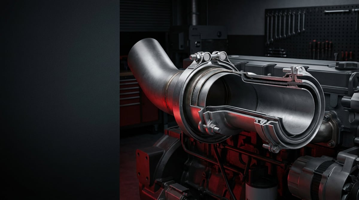
The exhaust line is one of the most neglected assemblies on a heavy commercial vehicle, and one of the most troublesome. A complaint that arrives at the workshop as "there is a noise from the turbo" very often turns out to be a cracked flex connecting pipe or a loosened clamp. On Euro 5 and Euro 6 vehicles the issue is not only noise: even the smallest leak in the line can turn into an SCR efficiency fault, a torque-limiting fault code and an unplanned roadside stop. This guide explains how to diagnose an exhaust clamp and connecting pipe in the field, how to replace it correctly, and how to extend its service life.
What Is an Exhaust Clamp & Connecting Pipe? Function and Operating Principle
An Exhaust Clamp & Connecting Pipe is the joint assembly that seals the gas path between the exhaust manifold, the turbocharger outlet, the DPF/SCR module and the silencer on heavy commercial vehicles. The braided flexible pipe absorbs the 3-8 mm order of engine movement on its mounts and continuous exhaust temperatures of 450-650 °C, while the V-profile or U-bolt clamp secures the mating face typically within a 10-80 Nm band.
The Exhaust Clamp & Connecting Pipe assembly works by fulfilling two opposing duties at the same time: the line must be leak-tight, yet it must also remain free to move. The engine is attached to the chassis on mounts and moves constantly under load, at idle and during braking. The silencer and aftertreatment module, however, are fixed to the chassis. If nothing absorbs this relative movement, the stress passes straight into the weld seams and the manifold flange; the result is a broken stud, a cracked manifold or a split pipe.
The flexible connecting pipe absorbs that stress through its layered construction. Innermost is a liner (interlock or lamella layer) that guides gas flow and reduces internal friction; in the middle sits the bellows or spiral-wound stainless body that provides the actual flexibility; outermost is a wire braid sleeve that protects the body against impact, stone strike and overextension. Thanks to this triple construction the part accommodates both axial and angular movement without ballooning under pressure.
On the clamp side the job looks simpler, but the tolerance is tighter. The clamp seats the sealing face by squeezing two pipe ends or a flange with a defined circumferential force. Metal expands as temperature rises and contracts as it cools; the clamp is expected to carry thousands of these cycles without losing its grip. That is why band thickness, bolt class and material quality on heavy commercial clamps are very different from those of a standard hose clamp.
Main components of the assembly
- Spiral / bellows flexible pipe (flex): absorbs relative engine-chassis movement and thermal expansion.
- Wire braid outer sleeve: limits overextension and protects against external impact and stone strike.
- V-profile (V-band) clamp: common at turbocharger outlet, DPF and SCR module joints; centres the sealing face and applies even pressure.
- U-bolt clamp: used on slip-fit pipe-over-pipe joints, delivers high clamping force.
- Wide band sleeve clamp: provides circumferential sealing without crushing the pipe end and is highly serviceable.
- Flange gasket: graphite, wire-mesh reinforced or spherical (donut) type; selected according to temperature and face geometry.
- Hangers, rubber mounts and brackets: carry the weight of the line; once fatigued, the load passes directly into the flexible pipe.
Relationship with the emission system on Euro 6 vehicles
On Euro 6 vehicles (the heavy-duty emission framework under UNECE R49) the exhaust line is no longer merely a gas discharge pipe; it is a measurement line. It carries EGT temperature sensors, DPF differential pressure hoses and NOx sensors upstream and downstream of the SCR. These sensors assume they are measuring inside a closed volume. A small leak between the DPF and the SCR, or ahead of the NOx sensor, lets outside air into the line; the sensor reads lower NOx than expected, the engine control unit miscalculates SCR efficiency, and a fault code of the "SCR efficiency below threshold" type can trigger torque limitation. One of the most common misjudgements in the field is to blame the AdBlue injector or the NOx sensor first in this picture; in a leak test the fault usually turns out to be a clamp gasket.
Temperature, material and noise aspects
Material selection on Exhaust Clamp & Connecting Pipe components directly determines service life. Stainless grades are defined within the EN 10088 family; austenitic and titanium-stabilised grades are preferred in the hot zone close to the turbocharger, while more economical ferritic grades are used further downstream. The geometric principles of band-type clamps are described in the DIN 3017 family. On the noise side, ECE R51 noise regulation applies to the vehicle as a whole; a leaking exhaust line is not merely a comfort issue but a non-conformity that can be identified at inspection and in roadside enforcement. These standard families provide the general framework; the quality and dimensions of the part must be verified against the relevant OE catalogue.
| Joint type | Typical location | Sealing principle | Key advantage / limitation |
|---|---|---|---|
| V-profile (V-band) clamp | Turbocharger outlet, DPF and SCR module inlet | Conical flange pair + ring gasket | Good centring, reusable; leaks if the sealing face is damaged |
| U-bolt clamp | Slip-fit pipe-over-pipe joints | Circumferential crushing of the pipe | High holding force; generally single use because it deforms the pipe |
| Wide band sleeve clamp | Intermediate pipes, silencer inlet | Uniform circumferential pressure over a wide band | Does not crush the pipe, serviceable; correct diameter selection is critical |
| Bolted flange joint | Manifold outlet, hot zone | Graphite or wire-mesh gasket | Withstands high temperature; high risk of stud breakage |
| Spherical (donut) joint | Angled joints between manifold and front pipe | Spherical gasket + spring bolt | Tolerates angular misalignment; spring pressure decays over time |
| Spiral flexible connecting pipe | Between engine and chassis line | Welded end + clamp/flange | Absorbs movement and vibration; the braid opens up if overstretched |
How do you tell an Exhaust Clamp & Connecting Pipe has failed?
Exhaust Clamp & Connecting Pipe failure usually progresses in stages: first a faint hiss on a cold start, then a blowing sound that becomes pronounced under load, and finally visible soot traces and a warning lamp. The table below lists the symptoms most often seen in the field together with their likely causes.
| Symptom | Possible cause | Check / verification |
|---|---|---|
| Hissing on cold start, blowing sound that fades as the engine warms up | Clamp loosening or micro leak on the sealing face; partly closing as the metal expands when hot | Listen at idle with the engine cold; check joints by hand (while cold); a cold smoke test is preferable to soap foam |
| Metallic blowing noise increasing under load, often perceived as turbocharger noise | Crack in the flexible connecting pipe or opening of the braid | Raise the vehicle and inspect the pipe visually; scan joints and braid sleeve with a torch; flex it gently by hand and listen for a change in sound |
| Soot, carbon and dry black dust build-up at the joint | Ongoing leak; escaping gas is carrying carbon outwards | Clean the joint and re-inspect after a short test drive; if the soot trace reappears, the leak is confirmed |
| Exhaust smell in the cab, especially at idle and in reverse | Leak close to the engine bay; reaching the cab fresh air intake | Set cab ventilation to fresh air at idle and track the smell; make the leak point visible with smoke |
| Low SCR efficiency / NOx sensor rationality fault code | False air entering the line through a leak upstream of the sensor | Monitor live NOx and EGT data with a diagnostic tool; apply a pressurised smoke test to the DPF-SCR section |
| DPF differential pressure fault or regeneration failing to complete | Leak near the differential pressure hose connection; measurement is distorted | Check the differential pressure hoses and fitting ends; verify clamps along the line with a torque wrench |
| Vibration, a shaking sensation at the instrument panel at high engine speed | Flexible pipe has hardened or a hanger mount has failed; movement is transferred to the chassis | Load hangers and mounts by hand and check for free movement; press the pipe by hand and observe elastic return |
| Exhaust pipe sagging, sitting close to the ground, knocking noise | Hanger bracket broken or the pipe has slipped out because the clamp moved | Compare hanger count and position along the whole line against the OE layout; measure clearance between pipe and chassis |
| Unexplained increase in fuel consumption, loss of pulling power | Deviation in exhaust back pressure or torque limitation being activated | Read back pressure and derate status through the diagnostic tool; put the line through a leak test |
Locating the leak with a smoke test
The most reliable way to detect Exhaust Clamp & Connecting Pipe leaks is a low-pressure smoke test. The line is temporarily blocked at a suitable point, controlled low-pressure smoke is introduced, and the joints are observed under a torch. This method makes visible those leaks that are too small to distinguish by ear yet large enough to distort sensor readings. The procedure must always follow the service instructions so that pressure never exceeds the manufacturer limit and the aftertreatment module is not damaged.
Cold-hot listening and hand checks
The cheapest method in Exhaust Clamp & Connecting Pipe diagnosis is listening to the vehicle while cold. Because cold metal has contracted, the leak is at its most pronounced; as the engine warms up, expansion partly closes the gap and the noise diminishes. This behaviour on its own is a strong indicator of a leak caused by a clamp or gasket. Once the engine has cooled completely, the joints are gripped by hand and gently worked; a joint that moves or has play is immediately suspect. Never carry out hand checks on a hot line.
Cross-checking with diagnostic data
In problems caused by an Exhaust Clamp & Connecting Pipe the fault code is usually misleading; the code points at a sensor while the defect is mechanical. The correct approach is to cross-check using live data: NOx values upstream and downstream of the SCR, EGT temperature differences and DPF differential pressure are read together. If there is an inconsistency between sensor values that cannot be explained physically (for example lower than expected NOx and low EGT under high load), the mechanical tightness of the line must be questioned before any sensor is replaced.
Symptoms such as sagging, knocking and vibration can come from the brackets carrying the line on the chassis; bracket types, mounting logic and maintenance are collected in our chassis mounting bracket failure and replacement guide.
Further reading
For a plain-language technical overview of this subject, see the reference article on Wikipedia. Always confirm specific figures and procedures against the vehicle manufacturer service data.
How is an Exhaust Clamp & Connecting Pipe replaced? Step by step
Exhaust Clamp & Connecting Pipe replacement is not a difficult operation when carried out in the right order; however, rusted studs, seized clamps and strained assembly are what make most of these jobs run long. The sequence below is designed so that the line does not build up stress again.
- Preparation and diagnostic record: Secure the vehicle, read and record the fault codes, and mark the leak point clearly before replacement. Inspect the entire line so you do not replace a single part and see the same complaint return.
- Disconnecting sensors and cabling: Carefully disconnect EGT and NOx sensors and differential pressure hoses in the area to be removed. Release the connector locking tabs, do not force the cable by pulling on it; protect the sensors against contamination and photograph the removal sequence for reference.
- Applying penetrating fluid and waiting: Apply penetrating fluid to clamp bolts, flange studs and nuts and wait at least 15-20 minutes. Skipping this step is the main cause of the stud breakages most often seen in the field.
- Supporting the line: Before removal, support the pipe and silencer from below with a jack or support stand. An unsupported line can drop under its own weight when the last bolt is released and tear off neighbouring hangers and sensors.
- Removing clamp and flange joints: Loosen the bolts gradually and in an alternating (crosswise) sequence. Do not force the band on seized V-profile clamps; cut it if necessary and fit a new one. U-bolt clamps are considered already deformed, so removed ones are not reused.
- Removing the old part and comparing: Take out the old connecting pipe and lay it beside the new part to compare overall length, outside diameter, end form, flange hole pattern and angular orientation. Even a single dimension that does not match will force the installation and shorten the life of the part.
- Surface cleaning: Mechanically remove old gasket residue, carbon and rust from flange and pipe seating faces. Use a suitable scraper that will not score the surface; remember that deep scratches will leave a residual leak. Replace broken studs at this stage.
- Fitting new gaskets and clamps: Always fit new gaskets, clamps and, where used, self-locking nuts. Seat the gasket in place and slide the clamp on loosely. If required, use only the high-temperature assembly paste approved by the manufacturer, in the specified area and as a thin layer.
- Loose assembly and alignment: Fit all joints by hand first, leaving them loose. Seat the line on its hangers and check that clearance between the pipe and the chassis, air reservoir, wiring harness and fuel line meets the distance specified by the manufacturer. Never force the flexible pipe into position by pulling or bending it.
- Progressive torquing: Once alignment is verified, tighten starting from the engine end and working rearwards. Using a calibrated torque wrench (calibration tracking is recommended for torque tools within the scope of ISO 6789), tighten progressively, in a crosswise sequence and up to the value specified by the manufacturer. Secure the hanger brackets last.
- Testing, leak checking and clearing codes: Refit the sensors, start the vehicle and listen for leaks at idle. Then bring the engine to operating temperature and check again. Clear the fault codes, and after a short test drive confirm that the codes do not return and that live sensor data is consistent. Rechecking torque values once the line has cooled is good practice.
What are the most common mistakes when replacing an Exhaust Clamp & Connecting Pipe?
Most mistakes made when replacing an Exhaust Clamp & Connecting Pipe occur not during the fitting itself but in the logic of the fitting. Even if the part looks correctly installed, the stress accumulated in the line comes back a few thousand kilometres later as a new crack at the same point.
- Replacing parts without confirming the source of the leak: Noise does not always come from where the leak is; a replacement carried out without a smoke test usually moves the problem rather than solving it.
- Not using a torque wrench: The "I tightened it by hand, it will hold" approach leads to errors in both directions on an exhaust. Under-tightening leaves a leak; over-tightening deforms the band, crushes the pipe and renders the clamp permanently useless.
- Skipping the tightening sequence: Fully tightening joints one by one distorts the line. The correct method is to fit all joints loosely, verify alignment, then tighten progressively in a crosswise sequence.
- Neglecting hangers and mounts: A failed hanger mount is the most common hidden cause of a shortened flexible pipe service life. All hanger components must be checked when a new pipe is fitted.
- Removing sensors roughly: Forcing out a rusted EGT or NOx sensor permanently damages the thread in the pipe. Using penetrating fluid and the correct wrench is cheaper than the pipe replacement that follows.
- Using unsuitable sealing paste: General purpose silicone, or paste applied in an area where it is not permitted, burns and flakes off and can contaminate DPF and catalyst surfaces. Only the product and area specified by the manufacturer are valid.
- Checking dimensions only and ignoring the application: A pipe with a matching outside diameter is not the correct part if the end form or flange hole pattern differs. Verification must be made through the engine/chassis code and the OE reference.
- Finishing the job without refitting heat shields: If removed heat shields and insulation pieces are not refitted, the fuel line, wiring harness and air hoses are exposed to excessive temperature.
Exhaust Clamp & Connecting Pipe technical values and inspection points
Exhaust Clamp & Connecting Pipe values given below are general reference ranges commonly seen in heavy commercial vehicle applications. Exact application-specific values vary with the engine and chassis code.
| Parameter | Typical range / unit | Explanation |
|---|---|---|
| Continuous exhaust gas temperature | 450-650 °C | Typical operating band at turbocharger outlet and ahead of the aftertreatment module |
| Peak temperature (active regeneration) | in the order of 600-750 °C | Short-term rise during DPF regeneration; determines material selection |
| Exhaust back pressure limit | typically 20-70 kPa (0.2-0.7 bar) | Varies by manufacturer; exceeding the limit causes power loss and fault codes |
| Pipe outside diameter (heavy commercial) | approximately 50-152 mm (2"-6") | Varies by application; clamp diameter must match the pipe exactly |
| Flexible pipe axial movement capacity | typically ±3-8 mm | Design movement band; the braid and seam fatigue if it is continuously exceeded |
| Angular deflection tolerance | typically ±2-5° | Building a permanent angle into the assembly shortens service life significantly |
| Material grade | stainless grades within EN 10088 | Austenitic/stabilised grades in the hot zone, ferritic grades further downstream are common |
| Clamp band thickness | typically 1.0-1.5 mm | Thin passenger-car type bands are not adequate in heavy commercial applications |
| Clamp bolt class | usually 8.8 or stainless A2-70 | Important for resistance to loosening under temperature |
| Expected service life | approximately 200,000-600,000 km or 3-6 years | Varies with duty profile, road conditions and salt/corrosion exposure |
| Fastener | Typical torque band | Note |
|---|---|---|
| V-profile (V-band) clamp, M8 | approximately 10-20 Nm | Tightened progressively; excessive torque opens the band and permanently damages the clamp |
| V-profile clamp, M10 | approximately 18-30 Nm | Common on turbocharger and aftertreatment module joints |
| Wide band sleeve clamp | approximately 12-25 Nm | The aim is circumferential pressure without crushing the pipe |
| U-bolt clamp, M10 | approximately 35-55 Nm | Single use; removed clamps are not refitted |
| U-bolt clamp, M12 | approximately 55-85 Nm | Seen on large diameter heavy commercial lines |
| Flange nut / stud, M10 | approximately 35-60 Nm | Tightened progressively and in a crosswise sequence |
| Hanger bracket bolt, M8-M10 | approximately 20-45 Nm | Tightened last, after the line has been aligned |
For a quick check in the field the following points are sufficient:
- Is there any opening in the flexible pipe braid, broken wires, necking or bright chafing marks?
- Are there cracks or permanent deformation in the clamp band, or stripped bolt threads?
- Has dry black soot or a whitish leak trace formed at the joints?
- Do the hanger mounts still have their elasticity, and are there cracks in the brackets?
- Is the clearance between the pipe and the chassis, wiring harness, fuel line and air bellows sufficient?
- Are the heat shields complete and secure, or are they making vibration noise?
- Are there stored or pending exhaust/emission codes in the diagnostic tool?
How is an Exhaust Clamp & Connecting Pipe maintained and its life extended?
An Exhaust Clamp & Connecting Pipe rarely appears as a separate item on a maintenance list, so it usually goes unnoticed until it fails. Yet a few minutes of checking during periodic maintenance both extends the life of the part significantly and prevents more expensive DPF, SCR and sensor failures. Three main factors determine service life: assembly quality, whether the line is mechanically free, and corrosion exposure.
- Carry out a visual check at every periodic service. During oil and filter changes the vehicle is already on the lift, so scanning the line with a torch takes a few minutes and catches early cracks.
- Assess hanger mounts as a system, not as individual parts. A single fatigued mount transfers the entire vibration load to the flexible pipe. Treat the mounts as part of exhaust line maintenance.
- Do not overlook fatigue in the engine mounts. An engine that moves excessively drives every flexible element in the line beyond its design limit.
- Carry out a corrosion check after winter. Road salt causes rapid corrosion on non-stainless fasteners and clamp bolts; an inspection round in spring is a good habit.
- Monitor regeneration behaviour. Frequent and incomplete regenerations keep the line at high temperature longer than normal; this ages both the gasket and the flexible pipe rapidly.
- Confirm the torque of the new part at the first service. A new gasket beds in somewhat during the first thermal cycles; checking torque at the first periodic service prevents early loosening.
- Review the line after bodywork and equipment installations. Brackets added after tipper, crane or tank installation can strain the line; a clearance check should follow such work.
- Break the habit of postponing a leak. A small leak carries carbon outwards and erodes the neighbouring surface as well, turning over time from a single-part job into a section replacement.
When these checks are applied properly, the exhaust joint assembly needs replacing only a few times over the life of the vehicle. A neglected clamp, on the other hand, can be the first link in a far more expensive chain that starts with an inexpensive part and extends to torque limitation, incomplete regeneration and damage to the aftertreatment module. On an exhaust line the most economical approach is to find the leak while it is small and seal it with the right part at the right torque.
Application and compatibility: Vehicle compatibility catalogue · Engine compatibility catalogue
Related categories: Clamp · Exhaust Pipe
Main guide: What Is an EGR Valve? Failure Symptoms and Cleaning (Heavy Commercial Vehicles)
Tags
Frequently Asked Questions
- What happens if an exhaust clamp comes loose?
- When an exhaust clamp loosens, a small gas leak first appears at the joint; this leak is heard as a hiss when cold and as a blowing sound under load. As the process advances, carbon builds up at the joint, the sealing face wears and the pipe can slip off its axis. On Euro 6 vehicles a loose clamp also lets false air into the line, distorting NOx and DPF measurements; the result can be an emission-related fault code and torque limitation.
- Why does an exhaust flex pipe crack?
- An exhaust flex pipe usually cracks not because of a material defect but because it is carrying more movement than it was designed for. The most common causes are fatigued engine mounts, failed exhaust hanger mounts, permanent stress built into the line during assembly, and use of a part of the wrong length. In addition, road salt corrosion and stone strike from outside weaken the braid sleeve and accelerate cracking. If hangers and mounts are not checked when a new pipe is fitted, the same failure recurs quickly.
- Can an exhaust leak trigger the engine warning lamp?
- Yes, particularly on Euro 5 and Euro 6 heavy commercial vehicles it can. The exhaust line carries NOx, temperature and differential pressure sensors, and those sensors assume they are measuring inside a closed volume. A leak upstream of a sensor lets outside air into the line, the measurement no longer reflects reality, and the engine control unit records a fault relating to SCR efficiency or the DPF. For that reason the tightness of the line must be verified before any sensor is replaced.
- Can an exhaust clamp be reused?
- V-profile and wide band clamps can be reused to a limited extent if the band shows no deformation, cracking or corrosion and the bolt threads are sound. U-bolt clamps, on the other hand, clamp by permanently crushing the pipe and are therefore considered single use, so removed ones are not refitted. Self-locking nuts and gaskets must be renewed in every case. When in doubt, fitting a new clamp is always cheaper than the labour of a second removal.
- What could cause noise to continue after the exhaust pipe has been replaced?
- The most common cause of noise that persists after replacement is a second leak elsewhere; exhaust noise does not always come from its source, and focusing on a single joint is misleading. The second cause is a new gasket that has not seated fully, or torque that was not applied progressively and in a crosswise sequence. A third possibility is a heat shield or hanger bracket making vibration noise. In such cases the whole line should be scanned again by listening with the engine cold and by a low-pressure smoke test.
- How often does an exhaust connecting pipe need replacing?
- The life of an exhaust connecting pipe varies significantly with the duty profile; as a general reference, a range of approximately 200,000-600,000 km or 3-6 years is seen. In urban distribution, construction site and short-haul use the line sees more thermal cycles and vibration, so life approaches the lower end of the band. In long-haul use it can reach the upper end. The determining factor is not mileage but whether the line remains mechanically free and how much corrosion it is exposed to.
- How tight should an exhaust clamp be?
- Exhaust clamp torque varies with the type and bolt size; as a general reference, bands of approximately 10-30 Nm are seen on V-profile clamps, 12-25 Nm on wide band sleeve clamps and 35-85 Nm on U-bolt clamps. Tightening must be done progressively and in a crosswise sequence, not in one go. Under-tightening leaves a leak, while over-tightening deforms the band and renders the clamp permanently useless. For the exact value the current OE service manual of the vehicle prevails, and a calibrated torque wrench must be used.
- How do I select the correct exhaust connecting pipe?
- The vehicle model alone is not enough for selection. Engine code, chassis code, year of manufacture and aftertreatment module configuration must be assessed together, and where possible the OE reference number on the old part should be used. The catalogue can be searched by engine code or OE number. Before ordering, pipe outside diameter, overall length, end form and, where present, the flange hole pattern should be compared side by side with the removed part. A part whose dimensions match but whose end form differs is not the correct part.
- Is it dangerous to drive with an exhaust leak?
- Yes, driving with an exhaust leak is risky in several ways. A leak close to the engine bay or the cab fresh air intake can carry carbon monoxide into the cab, creating a direct health hazard for the driver. Hot gas striking the wiring harness, fuel line or air hose creates a fire risk. In addition, a leaking line raises the noise level of the vehicle and can lead to non-conformity with the noise requirements under ECE R51. Once a leak is identified, it should be rectified without delay.
- Is exhaust paste a permanent solution?
- No, exhaust paste is not a permanent solution on heavy commercial vehicles. Paste only makes sense when it is used in the area approved by the manufacturer, as a thin layer and together with the correct gasket. Paste applied to a cracked flex pipe or a deformed gasket face burns and flakes off at high temperature; the particles can contaminate DPF and catalyst surfaces. The permanent solution is to replace the damaged part with a new one of the correct dimensions and to tighten the joint to the correct torque.
Related Articles

Brake Caliper Mechanism: Camshaft, Bearings, and Return Spring
Inside the truck air disc brake caliper: how the camshaft, thrust bearings, return spring and automatic adjuster turn push-rod force into pad pressure.
Tachograph Explained: Driver Cards, Symbols, Rest Times
How tachographs work in trucks and buses: analogue, digital and smart types, driver and company cards, symbols, download rules and roadside checks.
ADR Guide: Vehicle & Driver Rules for Dangerous Goods Transport
Learn what ADR means for heavy trucks: hazard classes, required vehicle equipment, driver certification, orange plate labeling, and inspection documents.


