Caliper Guide Pin, Bushing & Bolt: Faults, Repair, Care
Learn how caliper guide pins and bushings seize, how to diagnose uneven pad wear, and the correct removal, greasing and torque steps for replacement.
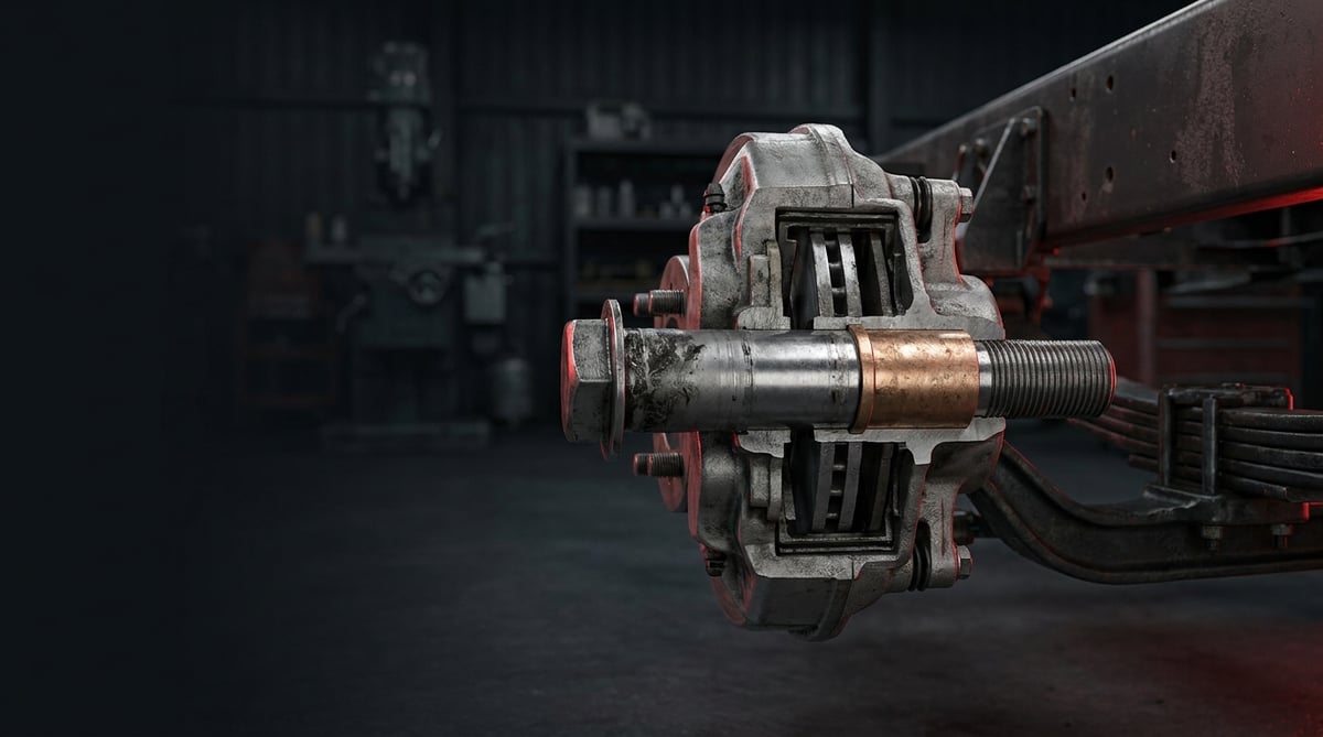
When the pads on one axle of a tractor unit have worn by markedly different amounts, when the disc has turned blue, or when the vehicle returns a low reading on a single wheel during a brake test, the technician usually looks at the pads and the disc first. In the field, though, the real culprit is normally a smaller group of parts: the guide pins, bushings and bolts that let the caliper slide on its carrier. The moment this group seizes, the caliper can no longer move freely, pad pressure piles up on one side, and the whole system begins to wear out in sequence. This guide explains, from a workshop point of view, the function of the guide pin, bushing and bolt group in heavy commercial vehicle disc brake calipers, its failure symptoms, the correct diagnostic sequence, the discipline required during removal and refitting, and the maintenance habits that extend its service life.
What Is a Caliper Guide Pin, Bushing & Bolt? Function and Operating Principle
The Caliper Guide Pin, Bushing & Bolt set is the assembly of guide pins, sliding bushings, boots and mounting bolts that allows the caliper body to move axially on its carrier in heavy commercial vehicle disc brakes. The Caliper Guide Pin, Bushing & Bolt group typically works with 25-40 mm of axial sliding travel over the life of a pad set and a guide pin bolt torque in the region of 30-60 Nm; the moment a boot starts to leak, service life shortens noticeably.
The operating logic of the sliding (floating) type disc brake caliper used on heavy commercial vehicles is simple: the brake chamber transmits clamping force to the mechanism on one side of the caliper, the pad on that side presses against the disc, and the reaction force slides the caliper body in the opposite direction to bring the outer pad onto the disc as well. In other words, both sides of the brake apply equal force only as long as the caliper can slide freely. The one thing that makes this sliding movement possible is the guide pin and bushing group.
In most applications the group consists of two pins, and those two pins do not do the same job. The long pin generally takes on the primary guiding role, while the short pin allows angular freedom and absorbs manufacturing and assembly tolerances as well as thermal expansion during braking. For that reason the bushing material and clearance value of the two pins may differ; the parts within the set are not interchangeable.
The system is not a mechanism that makes large, continuous movements. During normal braking the caliper moves less than a millimetre; the real long travel appears gradually as the caliper shifts to a new position while the pads wear. A sliding pair that moves little, endures harsh hot-cold cycles and is constantly exposed to water and salt — this is exactly the environment corrosion favours. That description also determines the failure character of the guide pin and bushing group: the part does not break, it seizes.
Which components make up the group?
- Guide pin: the pin on which the caliper slides, usually a surface-treated steel or corrosion-resistant coated pin.
- Sliding bushing: the bronze, steel or polymer/PTFE based bushing that determines the friction and clearance between pin and bore.
- Boot (bellows) and retaining ring: the sealing element that protects the pin against water, salt and dust — in practice the part that decides the life of the whole group.
- Cap / plug: the plastic or metal element that closes the outer mouth of the pin bore, single-use in most systems.
- Guide pin bolt: the bolt that fastens the pin to the caliper carrier, in most applications coated with a locking treatment and single-use.
- Caliper body/carrier bolts: high-torque bolts that fasten the caliper to the axle flange or carrier, frequently tightened by torque plus angle.
- High-temperature grease: the special grease specified by the manufacturer for the pin bore; ordinary lithium grease is not used in this area.
In which OE brake systems does it appear?
On heavy commercial vehicles the guide pin and bushing geometry depends far less on the vehicle make than on the brake system family built onto it and on the axle type. The most widespread applications in the field are the pneumatic disc brake families originating from Knorr-Bremse and Wabco/ZF, together with caliper installations of Meritor origin; each of these is used on truck, tractor, bus and trailer axles with different pin lengths and bushing arrangements. Vehicles such as the Mercedes-Benz Actros, Volvo FH, MAN TGX, DAF XF, Scania R series and Iveco Stralis carry different versions of these caliper families. These names are given only as application examples: the same vehicle model may have a different caliper — and therefore a different guide pin set — in different production years and axle configurations. The correct part is determined not by the vehicle model but by the caliper type and OE number.
Bolt property class and why single-use?
Caliper mounting bolts are high-strength fasteners; in the industry these bolts typically correspond to property classes 10.9 and 12.9 within the scope of ISO 898-1, and many of them are tightened close to the yield point using the torque-plus-angle method. A bolt tightened by that method stretches permanently; once removed, it will not deliver the specified preload if reused. In the same way, on bolts with a locking coating the coating does the job only during the first tightening. On the corrosion resistance side, coating performance is generally defined by the ISO 9227 salt spray test. Braking performance itself is assessed at vehicle level within the ECE R13 framework; a caliper that does not slide freely is measured directly as brake imbalance in that inspection. Which class, which coating and which tightening method apply to a given installation must be confirmed from the relevant OE catalogue.
| Guide arrangement | Typical installation | Characteristic behaviour | Service note |
|---|---|---|---|
| Long pin + short pin (classic two-pin arrangement) | Truck and tractor drive/front axles | The long pin guides, the short pin allows angular freedom | Pins and bushings are not interchangeable |
| Guide pin + fixed-bearing pin | Bus and some trailer axles | One side slides, the other side fixes the position | A difference in clearance is normal and should not be treated as a fault |
| Polymer/PTFE bushed arrangement | Modern lightweight caliper installations | Low friction, sensitive to grease type | Only the grease specified by the manufacturer is used |
| Metal (bronze/steel) bushed arrangement | Heavy loads and high thermal stress | Heat resistant, more sensitive to corrosion | Rapid seizure is seen after boot damage |
| Trailer / semi-trailer axle installations | Semi-trailer and tanker axles | Long standing periods, low brake usage | Standstill corrosion is seen most often here |
How do you recognise a Caliper Guide Pin, Bushing & Bolt failure?
Caliper Guide Pin, Bushing & Bolt failures almost always trace back to the same root cause: the boot tears, water and salt get in, corrosion forms between bushing and pin, and the caliper stops sliding. The symptoms then show themselves as brake imbalance, uneven pad wear and overheating. The table below matches field symptoms with their probable causes and the method of confirmation.
| Symptom | Probable cause | Check / verification |
|---|---|---|
| Inner pad noticeably more worn than the outer pad | Caliper is not sliding, clamping load piles up on one side; pin seized | Measuring pad thicknesses separately; axial movement test of the caliper by hand or with a lever |
| One end of a pad worn more than the other (tapered wear) | One pin has seized, the caliper is running at an angle | Checking free movement of both pins separately; looking for rub marks in the carrier bore |
| Vehicle pulls to one side under braking, brake imbalance on the axle | The caliper on one wheel is not free, brake force is low | Axle-based force comparison on a brake tester, inspection data within the ECE R13 framework |
| One wheel rim noticeably hot after driving, smell of burning | Caliper is not releasing, pad is rubbing on the disc (brake drag) | Wheel temperature difference across the axle with an infrared thermometer; free rotation check |
| Torn or swollen boot, grease leakage or blackened grease | Loss of sealing; water and salt entering the bushing bore | Visual inspection of the caliper from above and below; checking whether the boot lip has come off the retaining ring |
| Blueing, heat cracks or polishing on one face of the disc | Overheating caused by a continuously rubbing pad | Inspecting both disc faces separately; thickness and run-out measurement |
| Slow release after the brake is applied, light rubbing noise | Sliding resistance has increased; bushing swollen or grease hardened | Raising the vehicle and comparing free wheel rotation before and after braking |
| Rust streaks or signs of loosening around the caliper bolt | Bolt has lost its preload or has been reused | Position check with a marker line; breakaway torque check with a torque wrench |
| Brown dust in the pin bore, resistance during removal | Corrosion product has built up, the bushing-pin pair has locked | Visual inspection inside the bore during removal and examination of the pin surface |
Free sliding test
Caliper Guide Pin, Bushing & Bolt diagnosis is fastest with the free sliding test carried out by hand. Once the vehicle has been safely raised and the wheel removed, the caliper body is pushed and pulled in the axial direction; in a healthy group the caliper moves without effort, without catching, and with similar force in both directions. Catching in one direction, jerky progress or no movement at all indicates seizure. During the test, look at the character of the movement rather than its amount: a small but smooth movement can be normal, while intermittent, forced movement is always abnormal.
Verification by temperature difference
Caliper Guide Pin, Bushing & Bolt related drag is very clearly visible with an infrared thermometer after a short test drive. The two wheels on the same axle should be at similar temperatures in normal driving; if one side is noticeably hotter, the brake on that wheel is not releasing. Take the measurement from the disc and caliper area rather than the wheel hub, and keep the measuring points identical on both sides. This method is the earliest warning that catches the problem before pad wear even appears.
Pad thickness map
Caliper Guide Pin, Bushing & Bolt failure shows its clearest evidence on the pads. Measure the thickness of the inner and outer pads separately, and moreover at the leading and trailing end of each pad, and draw up a map for one axle. A large difference between inner and outer shows that the caliper is not sliding, while a difference between the two ends of a single pad shows that the caliper is running at an angle. The picture encountered most often in the field is the inner pad being noticeably more worn than the outer; when this picture appears, completing the pad change without checking the guide pin and bushing means the new pads will be consumed just as quickly.
The second possible source of the uneven wear read on the pads is the adjuster and return assembly inside the caliper; that group is covered in the brake caliper mechanism: camshaft, bearings and spring guide.
Standards and further reading
This subject is governed by the equipment rules for air-braked commercial vehicles. In the United States the federal air brake standard, FMVSS 121 (49 CFR 571.121) defines the reservoirs, protection and timing a compliant system must provide, and Europe applies the equivalent limits of UNECE Regulation No. 13. For further detail, see the on-road braking performance requirement in 49 CFR 393.52. Always confirm specific figures against the current regulation and the vehicle manufacturer service data.
Outside the United States the equivalent duties sit in national law. In the United Kingdom, regulation 18 of the Road Vehicles (Construction and Use) Regulations 1986 requires every part of the braking system to be maintained in good working order. In Canada, air brake systems fall under the Motor Vehicle Safety Regulations, which contain CMVSS 121.
How is a Caliper Guide Pin, Bushing & Bolt replaced? Step by step
- Make the vehicle safe: Stop the engine, set the parking brake according to the operating instructions, chock the wheels and place the vehicle on stands of adequate capacity. On axles fitted with spring brake chambers, cage the chamber mechanically.
- Remove the wheel, clean and document the current condition: Free the area around the caliper, the pin caps and the bolt heads from dirt, salt and rust with a wire brush and a suitable cleaner; starting removal with a dirty surface carries abrasive straight into the bore. Before dismantling, measure and record pad thicknesses, disc thickness and the position of the caliper — this data is the only way to confirm the root cause of the failure afterwards.
- Remove the pads and retainers: Take out the pad retaining spring, its pin and the pads according to the manufacturer's procedure. Keep the pads separated and marked with the side they came from; the wear pattern is a continuation of the diagnosis.
- Remove the pin caps and bolts: Take out the caps with a suitable tool and loosen the guide pin bolts in stages. On seized bolts use penetrating fluid and patience rather than an impact tool; a snapped bolt multiplies the job many times over.
- Separate the caliper and withdraw the pins: Separate the caliper body from the carrier and never let its weight hang on the brake hose — support the caliper with a hook wire or a stand. If the pins resist as you pull them out of the bore, the inside of the bore is corroded.
- Inspect the bore and the carrier: Clean the pin bore of corrosion products and check the inner surface for steps, oval wear or cracks. On a carrier with a damaged bore a new pin will also seize before long; in that case the decision must be taken at caliper/carrier level.
- Verify the new set by comparison: Lay the new pins, bushings, boots and caps side by side with the old parts and compare diameter, length, boot lip and bushing type. Do not mix up the long and short pins; the parts within the set are position-specific.
- Apply the manufacturer's grease in the correct quantity: Apply only the high-temperature grease specified by the manufacturer, in the defined places and quantity. Excess grease forms a hydraulic cushion in the bore that prevents the pin from seating fully and swells the boot from the inside; ordinary lithium grease breaks down under heat and locks the bushing.
- Assemble in the correct sequence and torque: Seat the boots fully by their lips, place the pins in their bores without forcing them, and fit the caliper onto the carrier. Always fit new guide pin and caliper bolts and tighten them to the value stated by the manufacturer, in two stages if torque plus angle is required. Tightening without a torque wrench is not acceptable on this group.
- Refit the pads and verify free movement: Put the pads and retainers back in place, operate the adjuster mechanism according to the procedure, and check the axial free movement of the caliper by hand once more. If any catching is felt, the assembly is not considered complete.
- Test and carry out a second check: Fit the wheel and tighten the wheel nuts to the specified torque, raise system air pressure and check that the brake holds, then carry out a short test drive. After the drive, compare wheel temperatures across the axle and re-check the wheel nut torque after the first hundred kilometres.
What are the most common mistakes when replacing a Caliper Guide Pin, Bushing & Bolt?
- Changing only the pads and skipping the guide pin and bushing check: Because the cause of the uneven wear has not been removed, the new pads are consumed just as quickly.
- Leaving the boot with a "small tear, it will do": The boot is the single part that determines the life of this group; a torn boot means a seized pin before long.
- Using the wrong grease: Ordinary lithium or copper based grease breaks down at the temperatures in the brake area and locks the bushing; only the grease specified by the manufacturer is used.
- Overfilling with grease: Grease trapped in the bore prevents the pin from seating fully and swells the boot from the inside until it comes off its lip.
- Mixing up the long and short pins: The two pins do different jobs; if they are swapped, the caliper either cannot slide freely or runs with excessive clearance.
- Hanging the caliper on the brake hose: The inner braid of the hose is damaged; the damage appears not during assembly but months later under pressure.
- Feel of the hand or an impact tool instead of a torque wrench: Overtightening deforms the pin bore, undertightening leads to loosening; both directly affect brake safety.
- Working on one wheel only: The opposite side of the same axle has experienced similar age and environmental conditions; it should at least be checked.
- Blowing brake dust off with compressed air: This is a respiratory risk; wet cleaning or an extraction system must be used.
- Fitting a new set into a damaged bore: In an oval or stepped bore the new pin will also seize before long; the decision must be taken at caliper/carrier level.
Caliper Guide Pin, Bushing & Bolt technical values and inspection points
The Caliper Guide Pin, Bushing & Bolt values given below are general reference ranges commonly encountered in heavy commercial vehicle pneumatic disc brake applications. Caliper family, axle type, production year and equipment level change these ranges; for exact data always refer to the vehicle manufacturer's current service manual.
| Parameter | Typical range (general reference) | Note |
|---|---|---|
| Caliper axial sliding travel (over pad life) | 25–40 mm | Varies with the caliper family and pad thickness |
| Guide pin diameter | Approximately Ø25–Ø40 mm | Long and short pins may differ in diameter; measure with a caliper gauge |
| Brake system supply pressure | 7.0–8.5 bar (100–125 psi) | What makes the caliper work is not pressure but freedom to slide |
| Disc/caliper area temperature in normal driving | 100–250 °C | On a long descent the disc face can exceed 400 °C |
| Temperature difference between wheels on the same axle | A noticeable difference is considered abnormal | Infrared measurement must be taken from the same point |
| Remaining friction material thickness limit | Typically in the region of 2 mm | The limit value is manufacturer specific and taken from the manual |
| Disc wear limit (typical 22.5" ADB installation) | New approximately 45 mm, limit approximately 37 mm | Thickness and crack criteria are confirmed from the manufacturer's table |
| Boot and cap condition | Untorn, dry, lip fully seated | Caps are single-use in most systems |
| Inspection interval (visual) | At every pad check and at scheduled maintenance | In fleet use, an additional check after winter is recommended |
| Fastening point | Typical torque band (general reference) | Application note |
|---|---|---|
| Guide pin bolt | 30–60 Nm | Torque plus angle in some systems; the bolt is always renewed |
| Caliper body – carrier mounting bolt | 180–300 Nm or torque plus angle | Sequence and stages are manufacturer specific |
| Caliper carrier – axle flange bolt | 250–450 Nm + angle | High property class, treated as single-use |
| Pin cap / boot retaining ring | By hand, in the region of 10–20 Nm | Overtightening cracks the plastic cap |
| Pad retaining pin and spring elements | Manufacturer specific low torque | A deformed spring element is renewed |
- Does the caliper slide axially without effort and without catching?
- Are the inner and outer pad thicknesses close to each other, and is there tapered wear on any single pad?
- Are there tears, swelling, hardening or grease leaks on the boots?
- Are the pin caps in place and intact, and has water entered the bore?
- Are there rust streaks, marker line shifts or signs of loosening on the bolt heads?
- Is there blueing, heat cracking or polishing on one face of the disc?
- After the test drive, are both sides of the same axle at similar temperatures?
- When the brake is released, does the wheel turn freely, or is there a rubbing noise?
How is a Caliper Guide Pin, Bushing & Bolt maintained and its life extended?
The Caliper Guide Pin, Bushing & Bolt group has no fixed replacement interval; what determines its life is sealing, grease quality and assembly discipline. A group with an intact boot, fitted with the correct grease and with its bolts properly torqued is one of the longest-lasting parts on the vehicle. A group that works on salted winter roads, has a torn boot and was not checked during a pad change, on the other hand, can seize within a single season. The habits below are the maintenance items that make the biggest difference in the field.
- Guide pin check at every pad change: A pad change is the natural, cost-free opportunity to check sliding freedom; skipping it is the most common maintenance mistake.
- Renewing the boot early: If a torn or hardened boot is replaced before the pin has seized, the whole group is saved.
- Right grease, right quantity: Only the high-temperature grease specified by the manufacturer must be used, and the quantity must follow the procedure.
- Extra check after winter: Salt and moisture are the main triggers of corrosion; a visual check at the end of winter catches seizures early.
- Moving vehicles that stand for long periods: Standstill corrosion is widespread, especially on trailer and semi-trailer axles; periodic movement and brake use reduce it.
- The habit of temperature scanning: In fleet maintenance, an axle-based temperature comparison with an infrared thermometer catches the fault before the pads wear.
- Thinking at axle level: If there is seizure on one wheel, the opposite side has experienced the same environment; the two should be assessed together.
- Renewing bolts and caps: Reusing elements that are treated as single-use is the most expensive failure arising from the cheapest part.
- Monitoring after the job: After every job that touches the brake system, torque and temperature checks must be repeated within the first hundred kilometres.
In fleet operations the most efficient approach is to treat the guide pin and bushing group not as a single part but as a maintenance kit. Renewing the pins, bushings, boots, caps and bolts in the same service visit on a vehicle that is already in for pad or disc work is markedly more economical when compared with the cost of bringing the vehicle back to the workshop a second time a few months later. It should also be remembered that a seized caliper affects not only its own pads but also the disc, the brake balance of the opposite wheel and ultimately fuel consumption.
Related categories: Pin · Bushing · Bolt · Cover
Main guide: Air Disc Brake Caliper: Faults, Replacement & Maintenance Guide
Tags
Frequently Asked Questions
- What happens when a caliper guide pin seizes?
- Because the caliper cannot slide freely, brake pressure is not distributed equally between the two pads. As a result the inner pad wears rapidly, the outer pad hardly wears at all, the disc overheats on one face and the brake force at that wheel drops. At a later stage the pad is in constant contact with the disc, so the wheel heats up and a burning smell and brake imbalance appear.
- When are the caliper guide pin and bushing replaced?
- There is no fixed mileage interval. The replacement decision is made according to condition: the set is renewed if the boot is torn, if the caliper does not slide freely in the axial direction by hand, if the inner and outer pads have worn by a marked difference, or if the pin resists during removal. In practice, the most appropriate moment is when signs of seizure are seen during the check carried out at a pad change.
- Can caliper bolts be reused?
- In most heavy commercial vehicle applications they cannot. The great majority of caliper and guide pin bolts are tightened close to the yield point with the torque-plus-angle method or carry a locking coating; in either case the bolt cannot deliver the same preload after the first tightening. Replacing them with new bolts once removed is the rule, and the exact requirement is stated in the vehicle manufacturer's service manual.
- Which grease is applied to a caliper guide pin?
- Only the high-temperature brake grease specified by the caliper manufacturer is used; these greases are generally silicone or synthetic based and are chosen to be compatible with the bushing material. Ordinary lithium or copper based greases can break down and harden at the temperatures found in the brake area and lock the bushing. The quantity of grease also matters: excess grease is trapped in the bore and prevents the pin from seating fully.
- Why does the inner pad wear more than the outer one?
- This picture is almost always caused by the caliper not being able to slide freely. On a floating caliper the outer pad is brought onto the disc only by the caliper body sliding back; when the pin seizes this movement does not take place and the inner pad carries most of the braking load. Whenever a difference between the pads is seen, the guide pin, bushing and boot must be checked.
- Does caliper seizure increase fuel consumption?
- Yes, indirectly but measurably. A caliper that does not release keeps the pad in constant contact with the disc; this continuous friction creates drag and makes the engine work harder to hold the same speed. It also shortens disc and pad life and can unbalance tyre wear.
- How is the correct guide pin set selected?
- The vehicle model alone is not sufficient for selection. The determining factor is the caliper type: the type/label information on the caliper body, the axle position, the production year and, where possible, the OE reference number of the old part should be used together. Measuring the diameter of the old pin with a caliper gauge and its length with a rule and comparing them with the new part before ordering is the safest final step.
- Can a seized guide pin be rescued by heating?
- It is not an acceptable method. Heating permanently damages the surface treatment of the pin and the material structure of the bushing; reducing its diameter with abrasive paper enlarges the sliding clearance and causes the caliper to run at an angle. A seized group is renewed as a set and the condition of the pin bore is assessed separately.
- How long does a caliper guide pin replacement take?
- The main factors determining the time are access and the level of corrosion. A wheel done together with a pad change, where the bolts come out without trouble, is a job of a few hours in most applications. Where corrosion is heavy and the bolts require penetrating fluid and patience, or where damage is found in the carrier bore, the job can extend to half a day or more. Having the part in stock is the factor that most shortens the planned downtime.
- Is caliper seizure detected during a brake inspection?
- Yes, the place where it usually shows most clearly is the brake tester. The wheel with a seized caliper produces lower brake force than its counterpart on the axle, and this is measured as axle-based imbalance assessed within the ECE R13 framework. In addition, the wheel not turning freely after the brake is released is seen in the same test as residual drag.
Related Articles

Brake Caliper Mechanism: Camshaft, Bearings, and Return Spring
Inside the truck air disc brake caliper: how the camshaft, thrust bearings, return spring and automatic adjuster turn push-rod force into pad pressure.
Tachograph Explained: Driver Cards, Symbols, Rest Times
How tachographs work in trucks and buses: analogue, digital and smart types, driver and company cards, symbols, download rules and roadside checks.
ADR Guide: Vehicle & Driver Rules for Dangerous Goods Transport
Learn what ADR means for heavy trucks: hazard classes, required vehicle equipment, driver certification, orange plate labeling, and inspection documents.


