Clutched Air Brake Compressor: Faults, Replacement, Care
Clutched air brake compressors on trucks: how the clutch works, telling a slipping clutch from a worn compressor, replacement steps and torque values.
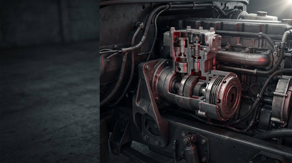
A fleet operator rarely meets the air compressor for a good reason: system pressure starts to build up late, the dryer cartridge spits oil, or an unfamiliar knocking noise comes from the engine bay. With clutched compressors one more heading is added to that picture — the clutch itself. The most common mistake in the field is blaming the entire compressor for a fault that originates in the clutch assembly, or the exact opposite, fitting only a new clutch to a compressor whose body is worn out. Written from the point of view of a technician working in heavy commercial vehicle service, this guide explains what a clutched compressor does, how it fails, the correct diagnostic sequence, the discipline of removal and refitting, and the maintenance habits that extend its life.
What is a clutched air brake compressor? Function and operating principle
A clutched air brake compressor is a piston-type air compressor that feeds the brake and auxiliary air system of a heavy commercial vehicle, is driven from the engine by gear or belt, and carries an electromagnetic or pneumatic clutch assembly placed between the drive and the crankshaft. When the system reaches cut-out pressure the clutch disengages and the compressor stops completely. In heavy commercial applications cut-out pressure is typically in the 10–12.5 bar band and compressor displacement varies between 250 and 720 l/min.
A conventional (continuously driven) compressor turns for as long as the engine runs. The pistons move even when no air is needed; the system merely switches to "unloaded" running with the discharge signal supplied by the pressure governor. This unloaded running continues to produce friction, oil consumption and heat. The clutched design cuts that loss at the root: when air is not required the drive connection is physically broken and the compressor does not turn.
The operating chain works as follows. The pressure governor, mounted on the air dryer or in a separate housing, continuously monitors system pressure. When pressure reaches the cut-out value the governor produces a signal; on electromagnetic types this signal interrupts the coil current through a relay or the vehicle electronic control unit, while on pneumatic types air pressure to the clutch piston is either applied or vented. As the signal changes, the connection between the clutch disc and the rotor is broken, the compressor crankshaft is released and it stops. When pressure drops to the cut-in value the process reverses, the clutch engages again and the compressor starts charging.
The heart of an electromagnetic clutch is the sub-millimetre air gap between the coil and the pressure disc. When the coil is energised, the magnetic field it creates overcomes the spring force, pulls the pressure disc onto the rotor and torque is transmitted by friction. As the friction surface wears over time this gap grows; beyond a certain point the magnetic force is no longer enough to pull the disc, and the clutch either does not grip at all or grips while slipping. A significant proportion of clutched compressor faults arise from this simple geometric change, which has nothing to do with the compressor body.
What is the difference between a clutched and a continuously driven compressor?
The difference lies in the behaviour when no air is being produced. In a continuously driven compressor the pistons keep moving during unloaded running, the bearings keep taking load and the oil film on the cylinder wall keeps heating up; meanwhile the air is vented through the unloader valve in the cylinder head or returned to the intake side. On the clutched type no rotating part remains in motion. This has three concrete consequences: a measurable improvement in fuel consumption because parasitic power loss disappears, a longer dryer cartridge life because oil carry-over is reduced, and a longer overhaul interval because mechanical wear is reduced. The size of the gain depends on the duty profile — in refuse collection or concrete mixer applications that consume air constantly the difference narrows, while on a long-haul tractor unit it becomes pronounced. Because the exact fuel saving varies with vehicle, route profile and air consumption, it should not be expressed as a single figure.
Clutch types: electromagnetic and pneumatic
The electromagnetic clutch works with the 24 V vehicle electrical system and its control can easily be handed over to an electronic control unit. Its maintenance advantage is that the fault is usually measurable: coil resistance, supply voltage and air gap are checked with three measurements. The pneumatic clutch, on the other hand, uses a separate air line and control valve; it is immune to electrical faults but exposed to line leakage, freezing and valve blockage. On both types the clutch assembly is built on a rotor with a bearing and a pulley or gear hub at the front of the compressor; bearing failure is the common weak point of both.
Components and auxiliary elements
- Clutch assembly: rotor/pulley, pressure disc (armature), coil, return spring and bearing.
- Compressor body: crankcase, crankshaft, connecting rod, piston and piston rings.
- Cylinder head and valve plate: inlet and delivery valves, unloader arrangement, valve springs, head gasket.
- Cooling circuit: water-jacketed body/head, inlet and outlet fittings and hoses (finned head on air-cooled types).
- Lubrication line: pressurised oil feed pipe from the engine and return line to the crankcase.
- Pressure governor and control line: generates the signal that engages and disengages the clutch.
- Delivery line: heat-resistant steel pipe or reinforced hose carrying the compressor outlet to the air dryer.
- Air dryer and cartridge: the component that traps moisture and oil vapour and directly reflects compressor health.
| Type | Drive / control | Behaviour when no air is needed | Typical application and service note |
|---|---|---|---|
| Continuously driven (clutchless) compressor | Gear or belt from the engine, permanently connected | Keeps turning; air is vented through the unloader valve and it runs unloaded | Common conventional solution; unloaded running keeps oil carry-over going |
| Electromagnetic clutched compressor | 24 V coil, signal from governor or control unit | Clutch disengages, compressor stops completely | Widespread on long-haul tractors and buses; coil and air gap are measurable |
| Pneumatic clutched compressor | Air pressure via a control valve | Clutch disengages, compressor stops completely | Immune to electrical faults; risk of line leakage and freezing |
| Energy-saving (unloading) compressor | Continuous drive plus advanced unloading system | Keeps turning but its load drops noticeably | Intermediate solution; does not give the full stop advantage of the clutched type |
The clutched compressor is mainly found on heavy commercial vehicles in engine families originating from Mercedes-Benz, MAN, Volvo, DAF, Scania, Iveco and Renault Trucks, mostly as part of Knorr-Bremse and Wabco type air brake architectures. These names are application examples only; even within the same engine family there are different part numbers according to emission generation, compressor displacement and clutch type.
How can you tell if a clutched air brake compressor has failed?
Clutched compressor faults gather at two separate addresses: the clutch assembly and the compressor itself. The first task in diagnosis is to make this distinction clear, because at first glance the symptoms of the two resemble each other. The table below matches field symptoms with probable causes and the verification method.
| Symptom | Probable cause | Check / verification |
|---|---|---|
| Air pressure does not build at all, the vehicle cannot release the park brake | Clutch never engages: open-circuit coil, no supply voltage, fuse/relay fault or no pressure in the pneumatic control line | Voltage measurement at the coil terminals, coil resistance measurement, pressure check in the control line; visual observation of whether the clutch is turning |
| Pressure builds but very slowly, charging time has increased | The clutch is slipping (air gap has grown, friction surface worn) or the compressor valve plate is leaking | Measuring the time to rise from empty tanks to cut-out pressure and comparing it with the manual value; checking the clutch surface for burnt smell and glazing |
| Metallic clack as the clutch engages and disengages, followed by repeated cycling | Unstable pressure governor signal, leakage in the system, clutch surface not seating evenly | Static pressure drop test with the engine stopped; reading governor cut-out and cut-in pressures on a gauge |
| Continuous humming or grinding from the clutch area, noise related to engine speed | The clutch bearing is fatigued or has run out of lubrication | Checking the pulley by hand for play and roughness while the compressor is disengaged; listening with a stethoscope |
| Oil coming from the air dryer cartridge and the tanks, oil deposits in the lines | Compressor piston rings or valve plate are passing oil; the compressor has overheated | Removing the line at the dryer inlet and inspecting its inner surface; draining the tank and monitoring the amount of oil |
| The compressor never stops, the clutch does not disengage despite cut-out pressure | The clutch disc is magnetically stuck, the spring is broken, the control signal is permanently active or the governor is faulty | Measuring coil voltage when cut-out pressure is reached; monitoring the governor output |
| Delivery line and dryer inlet extremely hot, carbon build-up | Continuous charging, restricted delivery line, insufficient cooling or system leakage | Measuring delivery line temperature with a non-contact thermometer; checking the line for blockage and crushing |
| Coolant level dropping, traces of moisture around the compressor | The water jacket gasket or head gasket is leaking | Pressure testing the cooling system; checking for dryness around the compressor head |
| Engine oil level falling with no visible external leak | Leakage in the compressor oil feed/return line, or oil passing from the crankcase to the delivery side | Checking the oil feed fitting; inspecting the dryer and tank for oil |
Is the clutch faulty or the compressor?
The quickest method for making the distinction is to see directly whether the compressor is turning. When the engine is started while system pressure is below the cut-in value, the clutch should engage and the compressor pulley and hub should turn together. If the hub is not turning the problem is on the clutch side and the electrical or air control is investigated. If the hub is turning but pressure is not building, the issue lies in the compressor itself or in the delivery line. This single observation prevents the large majority of unnecessary compressor replacements.
Diagnosis by measurement on an electric clutch
On an electromagnetic clutch, three measurements almost always lead to the answer. The first is coil supply voltage: at the moment of engagement, a value close to the nominal voltage of the vehicle system should be seen at the coil terminals; a noticeably low voltage means cable resistance or a poor earth. The second is coil resistance; an open-circuit coil gives infinite resistance, while a short-circuited coil gives a value far below what is expected. The third is the air gap: it is measured with a feeler gauge and grows as the friction surface wears. The acceptance limit for these values is manufacturer-specific and must be taken from the service manual.
Charging time and pressure test
The most honest measure of compressor performance is the time it takes for drained tanks to reach a specified pressure. This test makes clutch slip, valve leakage and system leakage visible at the same time. When taking the measurement it is essential that engine speed and the starting pressure of the tank comply with the conditions described in the manual. If the time has increased, the next step is to isolate the system and separate out the leak: after the engine is stopped, the pressure drop over a defined period is monitored. The framework for brake system performance and leak-tightness requirements is defined within ECE R13; for vehicle-specific acceptance values and measurement conditions, the relevant OE catalogue and service manual must be taken as the basis.
Standards and further reading
This subject is governed by the equipment rules for air-braked commercial vehicles. In the United States the federal air brake standard, FMVSS 121 (49 CFR 571.121) defines the reservoirs, protection and timing a compliant system must provide, and Europe applies the equivalent limits of UNECE Regulation No. 13. For further detail, see the illustrated reference guide at airbrakecompressor.com. Always confirm specific figures against the current regulation and the vehicle manufacturer service data.
Readers outside the United States should work from their own national framework: in the United Kingdom the braking system must be maintained under regulation 18 of the Road Vehicles (Construction and Use) Regulations 1986, and in India the governing rules are published by the Ministry of Road Transport and Highways.
How is a clutched air brake compressor replaced? Step by step
- Secure the vehicle: Park it on level ground, chock the wheels, secure the park brake appropriately and isolate the electrical system. On tilt-cab vehicles, raise the cab and lock the safety catch.
- Depressurise the system: Vent all air tanks through their drain valves and confirm on the gauge that pressure has returned to zero. Also release any residual pressure in the dryer and auxiliary circuits.
- Drain the coolant: On water-cooled compressors, drain the cooling circuit down to the level specified by the manufacturer. Do not open the cap before the system has cooled.
- Clean and mark the area: Clear dirt and oil from around the fittings to be removed using compressed air and a clean cloth. Label and, if possible, photograph the electrical connector, air and water hoses and the oil line before removing them. Cap all opened ports with clean plugs.
- Disconnect the connections: Remove the clutch supply cable or pneumatic control line, the delivery line, the oil feed and return pipes, the cooling hoses and the intake line if fitted, in sequence. Do not force the pipes with a spanner; hold the counter nut while undoing them.
- Support and remove the compressor: Carry the compressor with a suitable support or lifting device. Loosen the flange bolts gradually and in a crosswise sequence. On gear-driven types, watch the gear backlash during removal; on belt-driven types, release the belt tension first.
- Inspect the removed part and the drive side: Check for burning and glazing on the clutch friction surface, play in the bearing, wear on the hub, distortion on the flange face, tooth damage on the drive gear or run-out on the belt pulley. Carbon build-up on the inner surface of the delivery line shows that the compressor has overheated in the past; this line must be cleaned or renewed without fail.
- Verify the new compressor: Place the new part side by side with the old one and compare the flange hole pattern, the clutch type and coil voltage, the pulley/gear form, the direction of rotation, the positions of the inlet and outlet fittings and the cooling water passages. Confirm compatibility using the OE reference number; do not remove its plugs until the moment of installation.
- Fit and torque: Use a new gasket or O-ring and never reuse the old one. Seat the compressor without forcing it, start the flange bolts by hand, then tighten them crosswise and in stages to the torque specified by the manufacturer. On gear-driven types, set the gear backlash as described in the manual.
- Connect the lines and assess the dryer: Refit the oil feed and return line, the cooling hoses, the delivery line and the control connection. If the compressor was replaced because it was passing oil, the air dryer cartridge and the contaminated lines must also be renewed; otherwise the new compressor will run into a dirty system.
- Provide initial lubrication and start up: Prime the compressor with its first oil charge as specified by the manufacturer, or wait for the oil line to fill. Fill and bleed the cooling system, make the electrical connection and start the engine. Confirm by sight and sound that the clutch engages and disengages.
- Test and check: Drain the tanks and measure the charging time, read the cut-out and cut-in pressures on the gauge. Check for air, water and oil leaks at idle and at high engine speed. A cold check should be repeated after the test drive, and connection torques and leaks should be reviewed again at the first service interval.
What are the common mistakes made when replacing a clutched air brake compressor?
- Replacing the whole compressor for a clutch fault: With a fault caused by the coil, bearing or air gap, the body may be sound. The distinction must be made first.
- Fitting only a clutch to a compressor whose body is worn out: The opposite mistake is equally common; oil carry-over caused by piston rings and valves is not solved by renewing the clutch.
- Changing parts without finding the leak in the system: The reason a compressor cycles constantly is often not the compressor but a leaking line or brake chamber. If the leak is not eliminated, the new part will also fatigue early.
- Not checking the pressure governor: A governor that does not deliver the correct cut-out pressure will either never disengage a sound clutch or keep engaging it continuously.
- Reusing the old gasket or O-ring: A sealing element that has been compressed once will leak water, oil or air on the second installation.
- Tightening flange bolts by feel: Under-tightening means leakage, over-tightening means flange distortion and a crushed gasket; a torque wrench is mandatory.
- Refitting a carbonised delivery line without cleaning it: A narrowed line raises the delivery side temperature and fatigues the new compressor within the first months.
- Neglecting the oil line: A restricted or blocked oil feed line will destroy even the soundest compressor in a short time.
- Not bleeding the cooling circuit: An air pocket left in the water jacket leads to local overheating and head gasket failure.
- Not measuring the charging time after replacement: If the job is handed over without a measurement, a slipping clutch or a leak in the system goes unnoticed.
Clutched air brake compressor technical values and check points
Clutched compressor values given below are general reference ranges frequently encountered in heavy commercial vehicle air brake systems. Engine family, compressor displacement, clutch type and equipment level change these ranges; for exact data, the current OE service manual matching the vehicle's engine and chassis code must be consulted. For compressed air quality (moisture, oil and particle content) the ISO 8573-1 classification is a widely used reference framework; the target class of the system and the dryer cartridge interval must be verified from the vehicle manufacturer's documentation.
| Parameter | Typical range (general reference) | Note |
|---|---|---|
| System cut-out pressure | 10–12.5 bar (145–181 psi) | Determined by the governor; the clutch disengages at this value |
| Cut-in pressure | Approximately 0.6–1.5 bar below the cut-out value | If the difference is too small the clutch cycles frequently |
| Compressor displacement (theoretical) | 250–720 l/min | Selected according to vehicle class and air consumption |
| Compressor operating speed | Approximately 0.8–1.5 times engine speed, depending on drive ratio | The drive ratio is vehicle-specific; the gear or pulley ratio is verified from the manual |
| Clutch supply voltage (electromagnetic) | 24 V nominal vehicle system | There should be no noticeable voltage drop at the moment of engagement |
| Clutch air gap | Typically in the order of 0.3–0.8 mm | Measured with a feeler gauge; the acceptance limit is manufacturer-specific |
| Compressor oil feed pressure | Same line as engine oil pressure; a few bar at idle | Low oil pressure directly shortens bearing life |
| Delivery line outlet temperature (instantaneous) | Can rise to the order of 150–200 °C under load | Continuously high temperature causes carbonisation |
| Target air temperature at the dryer inlet | As low as possible, typically below 65 °C | High temperature reduces drying efficiency |
| Charging time (from empty tanks to cut-out pressure) | Vehicle-specific; compared with the manual value | If it has increased, clutch slip or leakage is investigated |
| System pressure drop (engine stopped, static) | Limited over a defined period and specified in the manual | Assessed against the leak-tightness requirements within the ECE R13 framework |
| Connection point | Typical bolt class band (general reference) | Application note |
|---|---|---|
| Compressor flange bolts (M8, according to bolt class, verified from the manual) | 20–30 Nm | Tightened crosswise and in stages |
| Compressor flange bolts (M10, according to bolt class, verified from the manual) | 40–60 Nm | With a new gasket; the flange face must be clean |
| Cylinder head bolts | Manufacturer-specific, in a staged sequence | If the sequence and stages are skipped the head distorts |
| Delivery line fitting | 25–45 Nm | Varies according to diameter and end form |
| Oil feed pipe banjo bolt | 15–30 Nm | A new sealing washer at every removal |
| Clutch hub centre bolt/nut | Manufacturer-specific; generally in the 30–60 Nm band | Differs according to clutch type, taken from the manual |
- Have the cut-out and cut-in pressures been read on the gauge and compared with the manual value?
- Does the clutch really disengage at cut-out pressure and engage at cut-in pressure?
- Has the clutch air gap been measured with a feeler gauge, and are there burn marks or glazing on the friction surface?
- Is there play, roughness or noise that can be felt by hand in the clutch bearing?
- Has the inside of the delivery line been checked for carbon build-up?
- Has the air dryer cartridge interval been exceeded, and is there any trace of oil at the cartridge outlet?
- Are the tanks drained daily, and is oil visible in the drained water?
- Is there any crushing, blockage or leakage in the oil feed and return lines?
- Are the cooling hoses sound, and are there traces of moisture around the compressor?
- Are the clutch supply cable, connector and earth connection free of corrosion and tight?
How is a clutched air brake compressor maintained and its service life extended?
Clutched compressor service life is determined by three things: uninterrupted lubrication, keeping the temperature on the delivery side under control, and the absence of unnecessary air consumption in the system. The most common early-failure picture in the field begins with the neglect of one of these three headings. A leaking brake chamber or a forgotten leak keeps the compressor engaged far longer than necessary; the clutch cycles more often, the friction lining wears faster, delivery temperature rises and oil carry-over increases. Most of the gain offered by the clutched design appears when the leak-tightness of the system is kept in good condition.
- Drain the air tanks regularly: Daily draining prevents accumulated water and oil from being carried back into the system. If oil is visible in the drained liquid, the compressor and the dryer must be assessed together.
- Change the dryer cartridge at its interval: A saturated cartridge cannot retain moisture; the mixture of moisture and oil accumulates both in the valves and in the brake components.
- Make leak hunting a routine: Brake chambers, fittings, quick connectors and brake chamber diaphragms should be checked regularly, and the static pressure drop test should be repeated periodically.
- Maintain engine oil and filter discipline: Because the compressor is fed from the engine oil line, an engine whose maintenance is neglected wears out the compressor along with it.
- Do not neglect cooling: On water-cooled types, make sure the hoses are clear and the circuit is free of air; a blocked water passage kills the compressor silently.
- Keep the intake side clean: The air filter or line feeding the compressor intake should be checked together with the engine air filter interval. A dirty intake is a direct cause of cylinder wear.
- Keep the clutch surface dry: Engine washing, oil leakage or spray lubricant must not reach the clutch friction lining.
- Check the electrical connection: A corroded connector and a loose earth cause low voltage to reach the coil and make the clutch grip while slipping.
- Come back at the first service after replacement: After a new compressor is fitted, repeat the torque, leak and oil checks at the first service interval.
On the fleet side, the most efficient approach is to plan the compressor not as a single part but as one link in the air production chain. Dealing with the delivery line, the dryer cartridge, the gaskets and sealing elements in the same workshop visit on a vehicle that comes in for compressor work is far more economical than the cost of taking the vehicle off the road a second time a few months later. Within a properly established maintenance routine, the clutched compressor is one of the long-lived components of the vehicle; when neglected, however, its failure does not remain limited to itself but spreads to the entire brake system.
VADEN ORIGINAL is an OE-quality manufacturer producing compressors and spare parts for heavy commercial vehicle air brake systems. Within our clutched compressor product family, versions for truck, bus and tractor unit applications, together with clutch parts such as coupling sets, clutch bodies and coupling shaft kits, plus compressor repair kits, gasket kits, valve plates and connection elements, are held in stock in a way that can be matched by engine code. You can search for the compressor suitable for your vehicle by engine code or OE reference number and place your order after verifying it with the compatibility information in the catalogue.
Related categories: With Clutch
Which parts restore body and head sealing, and when a kit is enough versus a full unit change, is explained in the compressor repair and gasket kit guide.
Main guide: Air Brake Compressor: Faults, Replacement & Maintenance Guide
Tags
Frequently Asked Questions
- What does a clutched compressor do and why is it preferred?
- A clutched compressor physically breaks the drive connection when air is not required, allowing the compressor to stop completely. In a continuously driven compressor, parasitic power, heat and oil carry-over continue while it runs unloaded; on the clutched type none of these occur. The result is a measurable improvement in fuel consumption, a longer dryer cartridge life and reduced mechanical wear. The size of the gain depends on the vehicle's air consumption profile.
- What should be done if the compressor clutch does not grip?
- First it must be established whether the clutch does not engage at all or engages while slipping. If it does not engage at all, the supply voltage, fuse and relay, coil resistance and, on pneumatic types, the control line pressure are checked. If it engages while slipping, the air gap is measured and the friction surface is inspected for burning and oil contamination. If the compressor body is sound, in most cases renewing only the clutch assembly is sufficient.
- If air pressure builds up slowly, is the compressor to blame?
- Not always. An increase in charging time can arise from three separate causes: clutch slip, leaking compressor valves, or an air leak in the system. The correct sequence is first to eliminate leakage with a static pressure drop test while the engine is stopped, then to confirm visually that the clutch really engages, and only last to assess compressor performance by measuring the charging time.
- Why does a compressor pass oil, and what causes the oil coming from the dryer?
- The main causes of oil carry-over from a compressor are piston ring wear, valve plate leakage, overheating and a restricted delivery line. Contamination on the intake side and a high operating temperature accelerate this process. Seeing oil in the dryer cartridge and the tanks is one of the earliest and most reliable indicators of the compressor's internal condition; once this finding appears, the dryer cartridge and the contaminated lines must be assessed alongside the compressor. Where leakage originates from the valve plate and piston rings and the body is sound, overhaul with a VADEN compressor repair kit and gasket set is often a viable option.
- Can the clutch assembly be replaced on its own?
- In many applications the clutch assembly is offered as a separate service part and can be renewed on its own while the compressor body is sound. To decide, the condition of the body must be assessed: if there is oil carry-over, low output or noise from the bearings, replacing the clutch alone will not be a lasting solution. The scope of the application-specific service part — clutch assembly, VADEN compressor repair kit, gasket set or complete compressor — must be verified from the OE catalogue and the VADEN parts list.
- How long does a clutched compressor replacement take, and how long is the vehicle off the road?
- What determines the duration is not the compressor itself but access. On an easily accessible, belt-driven installation the job can be completed in half a day, while on applications requiring cab tilting, draining of the cooling circuit and gear drive adjustment it can extend to a full day. To this must be added bleeding the cooling system, measuring the charging time and a second check after the test drive. Having the part ready in stock is the factor that shortens total downtime the most.
- Should the air dryer cartridge also be changed when the compressor is replaced?
- If the compressor was replaced because it was passing oil, yes. Oil carried into the system remains in the cartridge and the lines; if these are not renewed, the new compressor runs into a dirty system and the same fault picture repeats within a short time. If the compressor was replaced because of a mechanical fault (bearing, clutch, drive), the condition of the cartridge is assessed according to its interval. The inner surface of the delivery line should be checked in every case.
- What can cause the compressor to stay engaged constantly?
- The most common cause is an air leak in the system; the compressor runs continuously to make up for the leak and the clutch never disengages. The second cause is the pressure governor failing to deliver the cut-out signal. The third is the clutch being unable to disengage mechanically: a broken spring or a stuck disc creates this picture. The order matters — first the leak is looked for, then the governor, and the clutch is examined last.
- What should the clutch air gap be and how is it measured?
- The clutch air gap is the distance between the pressure disc and the rotor face, and it is measured with a feeler gauge at more than one point. In heavy commercial applications, values typically in the order of a few tenths of a millimetre are seen, in the 0.3–0.8 mm band as a general reference. The gap grows as the friction lining wears, and above a certain limit the clutch begins to slip. The acceptance limit and the adjustment method, where one exists, are manufacturer-specific; the vehicle manufacturer's current service manual must be taken as the basis.
- How do I choose the right clutched compressor?
- The vehicle model alone is not enough for selection. The engine code, chassis number, year of manufacture, clutch type (electromagnetic or pneumatic), coil voltage, pulley or gear hub form, direction of rotation and flange hole pattern must all be assessed together. The most reliable method is to search the OE reference number on the old compressor and, before fitting the new part, to place it side by side with the old one and compare the connection points.
Related Articles
Single vs Twin-Cylinder Air Compressor: Choice & Fitment
Learn how to match single or twin-cylinder air brake compressors to your truck: flow demand, drive and cooling interfaces, fault diagnosis, replacement steps.
Truck Air Compressor Overhaul Kit: Head, Valve Plate, Gasket
Compressor overhaul guide for heavy trucks: when to renew the cylinder head, valve plate and gaskets, fault diagnosis, torque values and fitting steps.
Air Brake Compressor: Faults, Replacement & Maintenance Guide
On a truck, a slow-filling reservoir or oil in the dryer often starts at the compressor's cut-in/cut-out cycle, not the compressor body: diagnosis and care.


