Truck Chassis Crack: Causes, Risk Assessment and Weld Repair Limits
What causes a truck chassis crack, how it's inspected and classified, and where stop-drill holes and weld repair reach their limit.

On a fleet inspection ramp, the first thing that draws the eye is rarely the crack itself. It's a thin paint blister on the outer face of the frame rail, just ahead of the rear axle bracket, tracked by a dry rust line running along it. Once that area is cleaned up, what's underneath is a hairline mark, almost ruler-straight: a fatigue crack that started at the edge of the lower flange and has been climbing into the web. The truck hasn't logged a complaint, and no warning lamp is lit on the dash. All the same, this crack sits in the vehicle's load-bearing skeleton, and it is not a defect that arrests itself. This guide isn't about the parts bolted onto the chassis; it's about the crack that starts in the chassis material itself — where and why it begins, how it advances, how it's found, and where a repair genuinely ends.
What Kind of Structure Is a Heavy Commercial Vehicle Chassis, and What Loads Does It Carry?
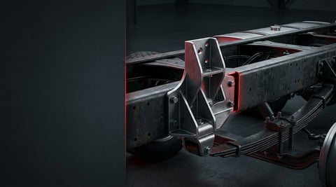
The chassis of a truck, tractor unit, bus or trailer is typically a ladder-frame structure: two frame rails running the length of the vehicle, tied together at intervals by crossmembers. The frame rails are usually C-section (channel) in profile — a horizontal flange at the top and another at the bottom, joined by a vertical web.
That cross-section explains most of what there is to know about where cracks form. Bending along the length of the vehicle generates tension and compression, and the flanges carry the bulk of that load; the web takes shear and part of the torsional load. In the loaded midsection of a vehicle, the lower flange works in tension and the upper flange in compression; directly over the axles, this pattern reverses. Because a fatigue crack starts where tensile stress is highest, the flange edges are also the zone where cracking is most often found.
The second defining fact is this: a heavy commercial vehicle chassis is deliberately designed to flex. When one axle drops into a pothole on rough ground, the frame's controlled twisting limits the stress that would otherwise land on the load and the suspension. Any modification that ignores this flexibility — any rigid connection that stiffens the chassis at a single point — piles up stress exactly where flexing is prevented. A significant share of chassis cracks trace back to precisely this cause, not to a material defect.
Why Do Cracks Start? Fatigue, the Notch Effect and Stress Concentration
The large majority of chassis cracks are fatigue cracks. Fatigue is damage that accumulates when a stress well below the yield point repeats often enough. In other words, what breaks a chassis isn't one overload event; it's ordinary loads repeating millions of times — every speed bump, every corner, every brake application, every load cycle, every twist. The damage builds up invisibly, and by the time it's visible, it has already progressed.
What decides where it starts is the notch effect. Stress spreads evenly across a uniform cross-section, but wherever that section changes — a drilled hole, a sharpened corner, a change in thickness, a surface scratch — stress piles up locally, and can run several times higher than the surrounding average. The features that create a notch on a chassis are well known: hole edges, sharp corners, section and thickness transitions, the toe of a weld bead, an arc strike, a grinding mark, a flame-cut edge, and a corrosion pit.
Damage runs through three stages. Inside the notch, a microscopic initiation forms first; this stage is invisible to the eye and takes up most of the component's total life. The crack then grows in a stable manner, advancing a small amount with every load cycle — this is the stage where inspection can actually catch it. In the final stage, the remaining cross-section can no longer carry the load and a sudden fracture follows; this last stage is very short and gives the driver no warning at all.
Where Do Chassis Cracks Start? Mapping the Risk Zones
Inspecting a chassis isn't about scanning the entire rail with equal attention; it's about looking where a notch actually exists. These zones vary from vehicle to vehicle, but the underlying logic doesn't: any spot where stress concentrates, or where flexing is restrained, is a candidate.
| Zone | What causes the crack | Typical appearance |
|---|---|---|
| Lower flange edge, between the axle and a crossmember | High tensile stress plus an edge notch | A straight line starting at the flange edge and climbing into the web |
| Hole edges, particularly holes drilled in the flange | Stress concentration around the hole, a burred edge | A radial crack running outward from the hole |
| The point where a weld bead ends | The weld toe is a sharp notch; the heat-affected zone is weaker | A crack running from the weld end into the base metal |
| Bracket connections, the last bolt or rivet | Flexing restrained at a single point, fretting as it loosens | A short crack from the fastener hole, a black ring mark |
| Around the spring hanger and suspension bracket | Where braking and drive reactions enter the chassis | A crack spreading from the bracket corner into the web |
| Under the fifth-wheel plate | Concentrated vertical and longitudinal load | Flange and web cracking level with the plate's corner |
| The end of an old repair or reinforcement plate | The reinforcement redirects stress rather than carrying it | A new crack right at the line where the plate ends |
This map calls for one scope distinction. In some of these rows, the crack originates in the bracket itself: cracking in the bracket body, loosening fasteners, worn bushings and bearing clearance belong to a separate fault family with their own diagnosis and replacement procedure, covered in the chassis mounting bracket guide. From here on, the subject is the crack that runs under or beside the bracket, in the chassis material itself, because the risk level and the repair decision for the two are entirely different. A bracket is a replaceable part; a frame rail is the vehicle's load-bearing structure.
On the tractor side, the area where the fifth-wheel plate attaches is its own concentration of risk; the plate transfers the trailer's vertical load, braking reaction and pulling force to the chassis through a limited number of points. The plate's own wear, play and locking mechanism are a separate maintenance topic covered in the fifth wheel and king pin guide; what concerns us here is the crack that appears in the chassis material itself in that area.
Fatigue Crack or Sudden Fracture? Reading the Fracture Surface
Understanding how a crack formed comes before deciding on a repair. Two cracks of the same length can have entirely different histories — one the result of months of fatigue, the other of a single overload event — and the two call for a different response. A fatigue crack is a process failure: if its cause isn't removed, the repair cracks again too. A sudden fracture is an event failure: it means other damage on the vehicle needs to be looked for as well.
The distinction is read from the fracture surface. A fatigue surface is generally smooth, matte and relatively flat, often showing progression lines — resembling a shell — spreading out from a single origin point. There's no significant plastic deformation. An overload fracture, by contrast, gives a rough, fibrous surface, with slanted, torn edges, and the surrounding metal is visibly deformed.
There are additional clues in the field. If the paint around the crack is still intact but a thin rust seep runs along the crack line, this is a fatigue crack that has been active for a long time. A wide area of flaking paint, a bent panel and elongated fastener holes, on the other hand, point to an impact or an overload event. Finding several independent hairline cracks on the same vehicle points to a third picture altogether: the problem isn't at a single spot but in the loading pattern or the body-mounting itself. Once fatigue is confirmed, other fleet vehicles of the same model and the same body should also be inspected on a targeted basis.
How Does a Crack Progress? Growth Direction, Acceleration and the Critical Threshold
A fatigue crack doesn't spread randomly; it advances perpendicular to the direction of the main tensile stress. On a frame rail, that mostly means: the crack starts at the edge of the lower flange, cuts across the flange, reaches the radius where the flange meets the web, and climbs from there up into the web. In some zones the starting point is a hole edge or a weld end instead, but the direction logic doesn't change.
The second property is acceleration. As the crack lengthens, the load-carrying section shrinks; the shrinking section carries higher stress; the higher stress increases the advance per cycle. In other words, the longer a crack already is, the less time it takes to add the next centimetre. The field judgement often heard — "it's been the same for months, it isn't growing" — is unreliable for exactly this reason; a crack cannot be assumed stationary unless it's actually measured.
The third property is that a crack of the same length carries a very different criticality depending on where it sits. A few centimetres confined to the flange edge, and the same length once it has cut fully through the flange and entered the web, mean entirely different things structurally. Once the flange is severed, the section that generates bending resistance starts to disappear; once the crack advances into the web, shear resistance drops too; and if it reaches the upper flange, the section is effectively split in two.
How Is a Chassis Crack Detected? Field and Workshop Inspection
The most common mistake in chassis inspection is looking at a dirty surface. Road salt, an oil film, thick paint and a crust of rust can hide a hairline crack completely. During cleaning, sandblasting and aggressive grinding are best avoided, since they can smear the surface and close the mouth of the crack; a degreaser, steam washing and controlled brushing give a safer result.
- Secure the vehicle on level ground, unload it where possible, and make sure there's safe access underneath; never work under a frame rail supported only by a jack.
- Clear the area to be inspected of oil, mud and loose rust, then dry it. A hairline crack can't be picked out on a damp surface.
- Scan the flange edges, hole surrounds, bracket and crossmember ends, and any weld toes with a strong, raking light source; light from the side reveals far more than light from above.
- Look for a linear paint blister, a dry rust line running along a crack, and a regularly spaced seep of dirt — all of these point to movement underneath.
- Check around rivet and bolt heads for a black ring, reddish wear dust, or looseness; a fretting mark shows that fastener is no longer carrying load and the load has shifted onto the neighbouring area.
- Apply liquid penetrant to any suspect mark: prepare the surface with cleaner, apply the penetrant, hold for the manufacturer's specified dwell time, wipe off the excess, and apply developer. If a crack is present, it shows up as a distinct line on the developer.
- Where a more sensitive result is needed and the equipment is available, move to magnetic particle inspection; on ferromagnetic chassis steel it also reveals cracks that sit very close to the surface.
- Once a crack is confirmed, find both ends of it; it's common for a crack to continue past its visible tip, and the repair decision is made against its true end point.
| Method | What it shows | Its limit and what to watch for |
|---|---|---|
| Visual inspection, raking light | Open cracks, paint blistering, deformation | Dirt, thick paint and rust hide a hairline crack underneath |
| Tracking rust and dirt marks | The line of a crack that has been active for some time | The mark doesn't give the crack's true length |
| Fastener inspection | Loosening, fretting dust, a shift in the load path | Not proof of a crack on its own |
| Liquid penetrant | The line and end points of a surface-breaking crack | Finds surface-open defects only; a dirty or oily surface gives a misleading result |
| Magnetic particle inspection | Surface and near-surface cracks | Requires trained application and correct magnetisation direction; residual magnetism must be removed afterward |
A commonly missed complement to the inspection is checking the running gear. A crack showing up around an axle usually means the load passing through that area has changed: a worn wheel-hub bearing, a wheel hub with play, a misaligned axle or a fatigued suspension component all change the vibration and reaction forces entering the chassis. If the crack is repaired without looking at this side of things, a repeat in the same area is common. For axle types and the symptoms of wheel-hub bearing failure, see the truck axle and wheel hub guide.
Further reading
For a plain-language technical overview of this subject, see the reference article on Wikipedia. Always confirm specific figures and procedures against the vehicle manufacturer service data.
Classifying the Crack and Deciding: What Does Each Finding Require?
What a crack means is determined by the answer to three questions: where in the cross-section it sits, how far it has progressed, and whether its cause has been removed. Any decision made without knowing these three is a guess. The table below offers a ranking for field assessment; the final call always belongs to the vehicle manufacturer's chassis repair instruction and a qualified technical assessment.
| Location and state of the crack | Risk level | Recommended approach |
|---|---|---|
| In the web, away from the flanges, short and single | Moderate | Both ends are located and measured, and a repair is planned within the manufacturer's instruction |
| Starting at the lower flange edge, partly through the flange | High | The vehicle isn't run loaded; an OEM-approved repair or rail replacement is assessed |
| Cut fully through the flange and climbed into the web | Very high | The vehicle is taken out of service; load-bearing capacity is compromised and it isn't driven |
| Affecting both the upper and lower flange together, splitting the section | Critical | The vehicle isn't used and is transported by tow; rail replacement comes into play |
| In a high-stress zone such as the fifth wheel, spring hanger or axle bracket | High to critical | Repair is restricted or prohibited by most manufacturers in these zones; no work is done without checking the instruction |
| A new crack at the end of a previous repair or reinforcement | High | The earlier repair was faulty; the reinforcement's geometry and end zone are reassessed |
The rule common to every row in the table is this: a repair isn't complete until its cause has been removed. Welding shut a crack that appeared at the base of a rigidly mounted body support, and leaving that same support exactly as it was, reproduces the same result in less time — because the fatigue strength of a repaired zone is usually lower than it was originally.
What Is a Stop-Drill Hole? What It Does and Doesn't Do
A stop-drill hole is a round hole drilled at the tip of a crack. The logic is simple: the tip of a crack is an extremely sharp notch, and it keeps advancing by concentrating stress at that very point. Drilling a round hole at the tip removes the sharp point and replaces it with a surface of a given radius, which lowers the stress concentration there; the crack's advance slows, or stops for the time being.
The method only works under one condition: the hole has to be drilled at the crack's actual tip. Where the visible mark ends often isn't where the crack has actually finished; a hairline extension usually continues a little further. For that reason, the tip shouldn't be drilled until it's been confirmed with penetrant or an equivalent method. A hole drilled short of the real tip does nothing at all — it can even add a second notch that feeds the crack.
In general practice, hole diameter runs from a few millimetres up to just under a centimetre, chosen by plate thickness and location; the binding figure is in the vehicle manufacturer's instruction. Once drilled, the hole's edge should be deburred, lightly chamfered, and protected against corrosion. Drilling is done with a twist drill; a cutting torch or a punch is never used, since both leave fresh stress and heat damage at the edge.
The most critical point here is what a stop-drill hole is not. It is not a repair: it doesn't restore lost cross-section, it doesn't raise load-carrying capacity, and it doesn't remove the cause of the crack. All it does is buy time — a temporary measure that can let the vehicle reach a service point in a controlled way. The permanent fix is the manufacturer-approved repair method, or renewal of the affected part. Once applied, it should be logged in the vehicle's file and the area re-checked at short intervals. Drilling into a flange is prohibited by many manufacturers, and a stop-drill hole should never be assumed to be an exception to that rule.
The Limits of Weld Repair: Why Can't Every Crack Be Welded?
Closing a chassis crack with a weld looks like the easiest fix on the shop floor, and is technically the most restricted. The restriction comes from the material itself. A frame rail's steel gets its strength from a controlled rolling and cooling process during manufacture. The heat that goes in during welding creates a heat-affected zone around the bead, and the microstructure there is locally disrupted; depending on the case, the result is softening, hardening and embrittlement, or a mix of the two. In short, welding can close a crack while lowering the material's strength right in that same zone.
Another constraint concerns direction. The general rule is that no welding is done on the flanges, or across the rail's axis. A transverse bead cuts straight across the direction where tensile stress is highest, and creates a line of weakness along that path. Where repair welding is permitted at all, the bead is usually planned on the web, run as vertically or diagonally as possible, and kept clear of high-stress zones. The permitted area, weld direction and off-limits zones are defined in the manufacturer's chassis repair instruction.
A further constraint sits in execution. Electrode choice isn't arbitrary: the general approach is a low-hydrogen consumable matched to the base metal's strength class. A consumable that has picked up moisture raises the risk of hydrogen-induced delayed cracking in the weld metal. Preheat, interpass temperature and cooling rate can't be left to guesswork either; an uncontrolled, fast cool leaves a hard, brittle structure. These parameters depend on material grade and thickness, not estimation.
The environment around the weld matters too. Arc strikes left outside the weld area are small but genuine crack starters. The point where the welding ground cable is attached should be chosen as close as possible to the work area; letting current find its way back through a bearing, a bushing, a gear or a wiring harness causes permanent damage to those components. Before welding, the battery connections and the control units for the brake and chassis electronics should be disconnected the way the manufacturer specifies; fuel lines, air lines, wiring harnesses and painted surfaces must be shielded from heat, and any lines running through the weld area moved clear beforehand.
Reinforcement Plate Logic and How the Wrong Reinforcement Creates a New Crack
A reinforcement plate is added to increase the section strength of a weakened area and spread the load over a wider surface. Done correctly, it works; done incorrectly, it produces the most common repeat-failure pattern seen in the field: the crack restarts right where the reinforcement ends. The reason is that a poorly designed reinforcement doesn't remove the stress, it relocates it; the point where the plate ends rigidly is a new notch, created by the sudden change in stiffness.
That's why what matters in a reinforcement isn't material thickness, it's end geometry and placement. Tapered, angled or rounded ends prevent the transition from being abrupt. Where the end lands matters just as much: a reinforcement shouldn't finish in a zone of high bending moment, right at the base of a bracket, or over a line of holes. It also shouldn't be so stiff that it eliminates the chassis's controlled flex altogether.
| Topic | Right approach | Common mistake and its result |
|---|---|---|
| Shape of the reinforcement's end | Tapered, angled or rounded end | A square-cut, abrupt end; a new crack right at that line |
| Length and placement of the reinforcement | A plate that clears the damaged area with margin, ending in a low-stress zone | A short plate that just covers the crack; a second crack right next to it |
| Attachment method | Mechanical fastening with bolts or rivets, where the manufacturer allows it | A continuous weld along the flange edge; a heat-affected zone and a line of weakness |
| Stiffness balance | A section that still allows the chassis's controlled flex | An overly thick, rigid plate; a crack where the flex is blocked |
| Hole pattern | Staggered layout, respecting edge and hole-spacing distances | Holes stacked in a straight line; tear-out along the hole line |
Where Drilling and Welding Are Banned on the Chassis
The most debated question in body and equipment mounting is drilling, and the rule can be summed up in one line: the flanges don't get drilled. The upper and lower flange are the actual section carrying bending load; every hole placed there both reduces the load-bearing area and creates a stress concentration at its edge. Where a hole is unavoidable, it goes in the web, kept a defined distance away from the radius where the flange meets the web. The minimum spacing between holes and from a hole to the edge, the largest permitted diameter, and the requirement to stagger holes rather than line them up are all set out in the manufacturer's body-mounting directive.
How a hole is made is part of the rule too. Holes are drilled; flame cutting, plasma cutting and punching are not accepted on a chassis, because they leave heat damage and micro-cracks at the cut edge. Once drilled, the hole should be deburred, lightly chamfered, and its corrosion protection restored. Using an existing factory hole is always preferable to drilling a new one.
Welding is subject to even stricter no-go zones. Around suspension brackets, spring hangers, axle mounts and the fifth-wheel plate — the high-stress areas — weld repair is generally restricted or banned outright. Straightening with a torch and heat-forming are likewise unacceptable on a chassis; localised heating permanently lowers strength and leaves damage that isn't visible to the eye. Cutting a chassis to lengthen or shorten it is its own operation and requires engineering sign-off in its own right.
The shared purpose of these rules is this: the chassis is not a mounting plate that can be freely worked on. The vehicle's strength calculations, load distribution, and braking and suspension behaviour are all based on the assumption that this structure remains intact. That's exactly why manufacturers such as Mercedes-Benz, Volvo, MAN, Scania, DAF, Iveco and Renault Trucks — and, on the North American side, brands like Freightliner, Kenworth, Peterbilt and International — publish detailed body-mounting directives; before any modification, the reference to check is the current directive for that specific vehicle model.
How Does Body and Equipment Mounting Create Cracks?
Behind the large majority of repeat chassis cracks in a fleet is body mounting. The reason traces back to the flexibility principle from the start of this guide: the chassis is designed to twist, while the body mounted on it usually doesn't want to. A subframe is what reconciles the two. Its job isn't just to carry the body; it's to spread point loads and transfer them smoothly into the main rail, while leaving a controlled path for the two structures to move differently from each other.
The general layout uses flexible or sliding connections near the front of the vehicle, where the chassis needs to twist, and makes the connection progressively more rigid toward the rear; the exact detail varies by body type and vehicle. The fasteners matter too: over-tightening a U-bolt clamp around the flange crushes it and leaves a permanent notch, while a loose one produces fretting wear. Both mistakes end at the same result.
The end of the subframe should be treated exactly like a reinforcement plate. A squared-off, abruptly ending tip creates a sharp jump in stiffness on the main rail, and a crack often appears right at that line. Tapering the end gradually, and not finishing it directly above the rear axle bracket, largely eliminates this pattern.
Cranes, tippers and tankers deserve their own mention, because they concentrate load at a single point: the zone where a crane's outriggers mount carries the high, variable moment generated while lifting, while on a tipper the entire load lands on the rear hinges and the rear section of the chassis during the tipping cycle. These vehicles need a shorter inspection interval than the rest of the fleet. Usage plays a role too: loading beyond capacity, loading unevenly to one side, and constant operation on rough ground all increase the stress amplitude reaching the chassis. When one of two otherwise identical vehicles keeps cracking and the other doesn't, the difference is usually this usage pattern, not a material difference between them.
Inspection, Roadworthiness and Record-Keeping
A chassis crack isn't only a technical matter; it also affects the vehicle's roadworthiness. At periodic vehicle inspection, cracks, breaks and non-compliant repairs in the load-bearing structure are treated as defects and, depending on severity, can fail the vehicle outright. In the EU this happens at periodic roadworthiness testing; in North America, the CVSA's North American Standard Inspection criteria list a cracked, cut or broken frame rail as grounds for placing a vehicle out of service on the spot. In practice, cleaning and reviewing the chassis ahead of a scheduled inspection avoids both surprises and an unnecessary re-visit.
The second issue is liability and record-keeping. A structural repair, even if it was correct on the day it was done, creates a blind spot later on if it isn't recorded: a technician who takes over the vehicle afterward has no way of knowing when, by what method, or for which crack the reinforcement under the paint was made. For that reason, every repair should be logged in the vehicle's file: the date of the finding, the crack's location and its measured length against a fixed reference, the method applied, the material used, who or which workshop carried it out, and any manufacturer approval obtained. Photographs of the finding and the repair are an integral part of that record.
A Crack-Monitoring Program for Fleets, and the Decision Summary
The only effective way to manage chassis cracking is not to repair a crack once it appears, but to look for it on a regular schedule. Because a fatigue crack goes through a long silent stage before it accelerates, the tighter the inspection interval, the earlier and the smaller the finding will be caught. A small finding leaves a wide range of options; a crack that has already split the section leaves only one.
- Add chassis inspection as a fixed line item on the periodic maintenance checklist, and shorten the interval for tippers, cranes, tankers and vehicles run on heavy off-road duty.
- Confirm any suspect mark with liquid penetrant and locate both ends of the crack; where the visible mark ends is not where the crack actually ends.
- Measure the finding, mark it, date it, photograph it, and log it in the vehicle's file.
- Assess the risk level from the crack's location and progression; don't run a vehicle loaded if a crack has cut through a flange or climbed into the web.
- Check the vehicle's OE chassis repair instruction before deciding on a repair; don't start work until the permitted zone, method and limits are confirmed.
- Where it's necessary and permitted, drill the stop-drill hole at the crack's actual tip, deburr the edge, and log the fact that this is a temporary measure.
- Investigate the crack's cause: the body mounting, the subframe end, a loosened fastener, the condition of the running gear, the loading pattern and the routes the vehicle runs.
- After the repair, protect the area against corrosion, set up a short-interval follow-up check, and inspect other vehicles of the same model on a targeted basis.
The chassis is the structure that everything built onto the vehicle rests on, and it has one property that sets it apart from other parts when it comes to cracking: it doesn't repair itself, it gives no warning, and it accelerates as it progresses. That's why the right approach isn't a repair reflex focused on closing the crack, but a three-step decision chain. First, establish where the crack is and how much of the section it affects; then find out why it started there; only then decide, using the method the vehicle's own manufacturer permits, between repair and renewal. Break that order, and the work done makes the crack invisible without removing it. In every case, the current OE chassis repair and body-mounting documentation for the vehicle's specific engine and chassis code is what governs.
Related categories: Support Bracket · Support Bracket · Chassis
Main guide: What Is a Wheel Hub? Wheel Bearing Failure and Symptoms
Tags
Frequently Asked Questions
- Why do chassis (frame) cracks happen on trucks?
- The large majority of heavy commercial vehicle chassis cracks are fatigue cracks: ordinary loads well below the yield point repeat millions of times and the damage builds up. A crack starts wherever stress concentrates in a notch — a hole edge, a sharp corner, a section change, the end of a weld bead, or a corrosion pit. Rigid connections that stiffen the chassis at a single point also pile up stress right where the frame is meant to flex.
- Where do chassis cracks most often appear?
- The most common location is the lower flange edge, where tensile stress is highest; the crack starts there and climbs into the web. Hole lines, section changes, weld ends, bracket and crossmember connections, the area around the spring hanger, under the fifth-wheel plate, and the boundary of a body mount are the other high-risk zones. The point where an old reinforcement plate ends is also a frequent site for a new crack.
- How do you tell a fatigue crack from a sudden fracture?
- A fatigue surface is smooth and matte, with progression lines spreading from a single origin point and no significant deformation around it. An overload fracture is rough and fibrous, with bent, torn edges and visibly deformed surrounding metal. The distinction matters: a fatigue crack is a process failure that returns if its cause isn't removed, while a sudden fracture is an event failure that means other damage should be checked for too.
- How is a chassis crack detected?
- The area is first cleared of oil, mud and loose rust and dried, since inspection on a dirty or damp surface isn't reliable. A strong, raking light is then used to scan flange edges, hole surrounds and weld ends for a paint blister or a dry rust line. A suspect mark is confirmed with liquid penetrant, and magnetic particle inspection is used where a more sensitive result is needed. A repair decision isn't made until both ends of the crack have been located.
- When shouldn't a truck with a cracked chassis be driven?
- A vehicle shouldn't be run loaded once a crack has cut partway through the lower flange, and it should be taken out of service once the crack has cut through the flange and climbed into the web. A crack affecting both the upper and lower flange together, splitting the section, means the vehicle isn't used at all and is moved by tow. Cracks in high-stress zones such as the fifth wheel, spring hanger or axle bracket also aren't driven on until the manufacturer's instruction has been checked.
- What is a stop-drill hole, and does it actually stop a crack?
- A stop-drill hole is a round hole drilled at the tip of a crack to remove the sharp notch that's driving it forward, which lowers the local stress concentration and slows or halts progress for the time being. It only works if it's drilled at the crack's real tip, which is why the tip is confirmed with penetrant first. A stop-drill hole is not a repair: it doesn't restore lost strength or remove the cause, it only buys time until a proper repair or replacement is done.
- Can a chassis crack be repaired by welding?
- Not every crack can be welded. A frame rail's strength comes from a controlled manufacturing process, and welding heat disrupts the material locally in a heat-affected zone. The general rule is no welding on the flanges or across the rail's axis; the permitted area, weld direction, consumable and thermal conditions are set out in the manufacturer's chassis repair instruction. Welding outside that instruction can lower fatigue strength and set up a more severe fracture later.
- Why does a reinforcement plate start a new crack?
- A poorly designed reinforcement doesn't remove stress, it relocates it: the point where a rigid plate abruptly ends becomes a new notch created by the sudden change in stiffness, and a fresh crack often appears right at that line. What matters is end geometry and placement rather than thickness — tapered, angled or rounded ends, a plate that clears the damaged area with margin, and an end point kept away from brackets and hole lines.
- Is it okay to drill or cut into a chassis?
- No. The general rule is that flanges are never drilled; where a hole is unavoidable, it goes in the web at a defined distance from the flange radius. Holes are made with a twist drill — flame cutting, plasma cutting and punching aren't accepted because they leave heat damage and micro-cracks. Straightening with a torch is also prohibited, and cutting a chassis to lengthen or shorten it requires engineering sign-off. The binding reference is the manufacturer's body-mounting directive.
- Will a vehicle with a chassis crack pass inspection?
- At periodic vehicle inspection, cracks, breaks and non-compliant repairs in the load-bearing structure are treated as defects and can fail the vehicle depending on severity; in North America, a cracked, cut or broken frame rail is grounds for an out-of-service order under CVSA roadside inspection criteria. Cleaning and reviewing the chassis before a scheduled inspection helps avoid surprises, and every structural repair should be logged with its date, location, method and any manufacturer approval.
Related Articles
Chassis Mounting Bracket: Failure, Replacement & Care Guide
Chassis mounting bracket guide for trucks and trailers: fatigue cracks, diagnosis, step-by-step replacement, bolt torque values and maintenance tips.

Truck Preventive Maintenance Checklist: PM A, B and C Intervals
How truck maintenance intervals combine mileage, engine hours and the calendar, plus the daily driver check and a system-by-system PM checklist.
ABS Brake System: How It Works, Warning Light and Faults
Learn how the ABS brake system works on heavy trucks, why the warning light comes on, how to diagnose sensor faults, and the correct replacement steps.


