Caliper Carrier & Guide Pins: Faults, Replacement, Care
How caliper carrier and guide pin wear causes uneven pad wear on trucks, how to test slide freedom, replace the kit step by step and grease it correctly.
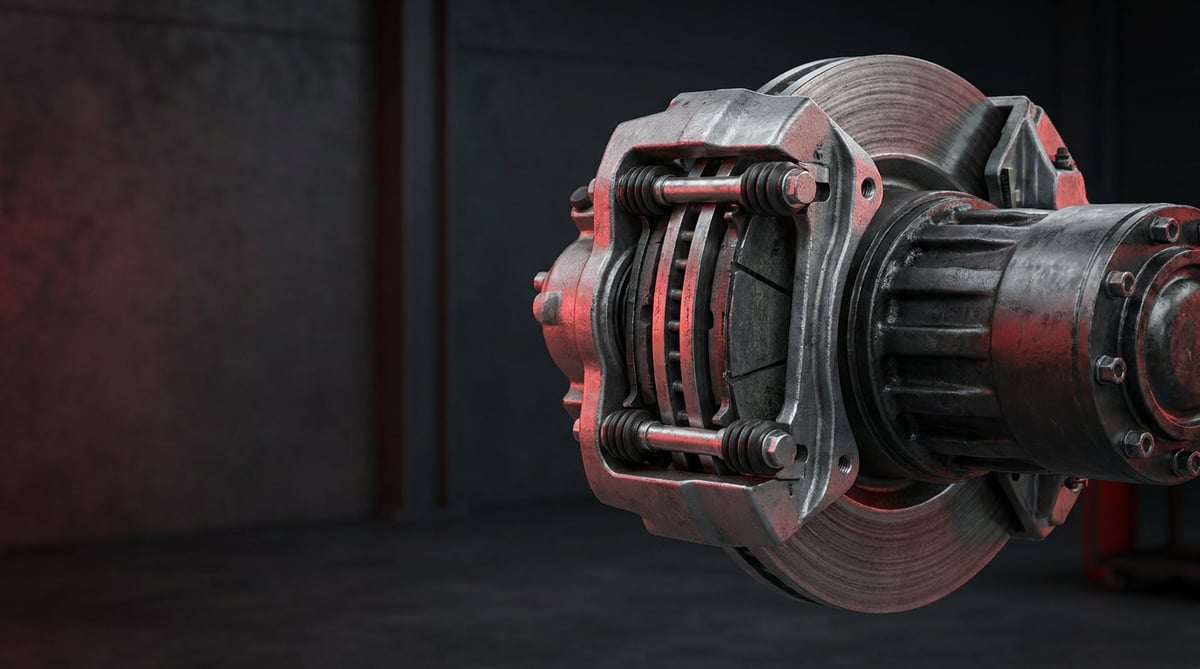
When a truck arrives at the workshop because the brakes "do not bite", the first parts inspected are usually the pads and the disc. Yet the picture most often found in the field is this: the inboard pad is worn down to the backing plate while the outboard pad still looks almost new. That is the classic sign that the caliper can no longer slide freely on its carrier. The caliper carrier and guide pin assembly is the least discussed part of a disc brake system, but when it fails it ruins both brake balance and pad and disc life. This guide explains what the assembly does, how it fails, the correct diagnostic sequence, the discipline required during replacement and the maintenance habits that extend its service life, from the perspective of a service technician.
What Is a Caliper Carrier & Guide Pin Assembly? Function and Operating Principle
The Caliper Carrier & Guide Pin assembly is the mechanical group in heavy commercial vehicle disc brakes that allows the caliper housing to slide axially on a carrier bracket bolted to the axle flange, while holding the pads in their abutments. The carrier transfers braking torque to the axle; the guide pins allow the caliper to slide freely, typically in the order of 1–3 mm. The guide pin repair kit is generally renewed every two to four pad sets, depending on operating conditions.
The air disc brake architecture widely used on heavy commercial vehicles works on the floating caliper principle. The force coming from the brake chamber presses only the inboard pad against the disc, through the adjuster mechanism and the tappets inside the caliper. The inboard pad bearing on the disc generates a reaction force, and this force slides the caliper housing on the guide pins towards the axle. The sliding housing pulls the outboard pad against the other face of the disc with its opposite bridge. In other words, what balances both faces of the brake with a single-sided force is the ability of the caliper to slide freely. Fixed calipers, which have opposed pistons on both sides of the disc, have no guide pin assembly; that is why, on a vehicle with floating calipers, the guide pin assembly is the first suspect when one-sided pad wear appears.
The carrier bracket has a two-layer function. The first is to take the tangential force generated during braking from the pad backing plate and transfer it to the axle flange; that is, the real torque path of the system runs through the pad abutments. The second is to carry the bearings in which the guide pins are seated, thereby guiding the axial movement of the caliper. When the brake is released, the forces that pull the caliper back are disc run-out, chamber return and the pad spring, and these forces are small; when friction in the guide increases, the return does not take place and the pad continues to rub lightly against the disc.
The assembly usually consists of two guide pins of different diameters. The long pin is the main guide and normally runs inside a steel or bronze bush; the short pin is mounted in an elastic bush or with wider clearance in order to compensate for manufacturing and assembly tolerances. Both pins are isolated from the environment by a boot (dust seal) and a cap. As soon as the sealing is lost, road salt, water and brake dust enter the bearing; corrosion starts and the caliper seizes step by step.
In which applications is the system found?
The caliper carrier and guide pin assembly differs according to the system family of the OE brake manufacturer. The air disc brake families most frequently encountered in the field originate from Knorr-Bremse and Wabco; these systems are used on applications such as Mercedes-Benz Actros and Atego, Volvo FH and FM, MAN TGS and TGX, DAF XF and CF, Scania R and S series, Iveco Stralis and S-Way, and to a large extent on trailer axles. These names are given only as application examples; even the front and rear axles of the same tractor unit may have different caliper sizes, pin diameters and boot shapes. The correct part is determined not by vehicle model but by axle type, caliper type code and OE number.
Standards and type approval framework
The performance and balance requirements of heavy commercial vehicle brake systems are defined under ECE R13 (braking of vehicles of categories M, N and O); the approval of friction components such as replacement pads and discs is carried out under ECE R90, while ISO 611 is the reference for brake terminology and measurement definitions. Although caliper carrier and guide pin kits are not a separate approval item in these regulations, they directly affect the balance and efficiency requirement of the vehicle under R13, and must therefore be selected in accordance with the OE dimensions and material class. The applicable standard and material class should be verified from the relevant OE catalogue.
Components of the assembly
- Carrier bracket (caliper carrier): the main body bolted to the axle flange, containing the pad abutments and the pin bearings.
- Long guide pin: the main guide; runs inside a bush and determines the axial movement.
- Short guide pin: the second guide that compensates tolerance; usually with an elastic bush.
- Guide bushes: steel, bronze or elastomer bearings.
- Boots (dust seals) and caps: sealing elements that protect the pin bearing from water, salt and brake dust.
- Pin bolts: the bolts that fasten the pin to the caliper housing, single-use in most applications.
- Pad abutment inserts and retainer spring/pin: ensure that the pad seats properly in its abutment and does not rattle.
- High temperature grease: specially formulated grease for the guide bearings, supplied by the manufacturer inside the kit.
| Application / axle | Caliper architecture | Typical guide pin layout | Characteristic service note |
|---|---|---|---|
| Tractor unit and truck front axle | Floating, single-sided actuation | Long + short pin, steel/bronze bush | Steering heat build-up and pulling to one side are reported here |
| Tractor unit and truck rear axle (drive) | Floating, single-sided actuation | Long + short pin, second pin with elastic bush | Thermal load is high; boot ageing accelerates |
| Bus axles | Floating | Short stroke, suited to a frequent braking profile | Urban stop-and-go duty tires the guide pins faster |
| Semi-trailer / trailer axle | Floating | Long + short pin, position exposed to corrosion | Long parking periods and road salt make seizure most common here |
| Fixed caliper applications | Fixed, opposed pistons | No guide pin assembly | One-sided wear is diagnosed differently |
How can a Caliper Carrier & Guide Pin fault be identified?
Almost all caliper carrier and guide pin faults lead to a single outcome: the caliper can no longer slide freely. This shows itself either as the pad rubbing continuously against the disc (friction, heat build-up, fuel consumption) or as the outboard pad not working at all (one-sided wear, loss of braking efficiency). The table below matches field symptoms with likely causes and the method of verification.
| Symptom | Possible cause | Check / verification |
|---|---|---|
| Inboard pad worn to the backing plate, outboard pad almost new | Caliper not sliding on the guide pins; corrosion or dried grease in the pin bearing | Measuring pad thickness separately; checking slide travel by pushing the caliper axially by hand |
| Outboard pad worn, inboard pad still sound | Caliper not returning, outboard bridge permanently loaded; one-directional binding in the guide | Checking the free clearance of the caliper after the brake is released |
| One wheel rim noticeably hotter than the others, smell of brakes | Continuous rubbing (brake drag); guide seized or water ingress into the boot | Comparing rim/disc temperatures per axle with an infrared thermometer after a test drive |
| Pulling to one side under braking, steering wandering on a straight road | Different braking force on the two sides of the same axle; guide locked on one side | Measuring the difference in braking force per axle on a brake tester (roller bench) |
| Guide pin boot torn, cracked or swollen; rust streaks around the pin | Loss of sealing, water and salt ingress into the bearing, grease washed out | Removing the wheel and checking the boots visually and by fingertip |
| Rattling from the caliper area on rough roads, slight knock under braking | Excessive clearance in the guide bearing, worn bush or ovalised pad abutment | Moving the caliper radially/axially by hand; measuring the clearance with a dial gauge |
| Uneven wear returning shortly after the pads were renewed | Guide pin kit not renewed during pad replacement, only the pads fitted | Assessing the wear direction of the removed pads together with the friction resistance of the guide |
| Blueing on one face of the disc, high density of heat cracks | Thermal overload caused by continuous one-sided contact | Examining both faces of the disc separately; measuring disc thickness from both faces |
| Signs of loosening, rust streaks or cracked paint on the carrier bolts | Loss of bolt torque or reuse of a single-use bolt | Checking the marker line and carrying out a check-tightening trial with a torque wrench |
Manual slide test: the fastest and most honest method
The most practical way to establish whether the caliper is free is to push the caliper housing back and forth in the axial direction, by hand or with a suitable lever, after the wheel has been removed and pad pressure released. A healthy assembly slides without resistance and springs back slightly when released. If the caliper does not move at all, the bearing has seized; a caliper that "moves if forced" is also unacceptable, because the force that pulls the caliper back when the brake is released is far smaller than the force applied by hand. The most common mistake in the field is to consider a caliper that only slides under force to be serviceable.
Reading the pad wear pattern
The removed pads are a free source of diagnostic data. The remaining thickness of the inboard and outboard pads must be measured separately. A clear difference between the two pads points to the guide pin assembly, whereas tapered wear on a single pad (thin at one end, thick at the other) generally indicates ovalisation of the pad abutment or a caliper sitting at an angle. Both pads being equally and heavily worn suggests, rather than the guide pins, a fault in the adjuster mechanism applying constant light pressure or a chamber that fails to return.
Verification by temperature and braking force
If doubt remains, measurement takes over. Immediately after a short test drive, the disc and rim temperature of each wheel is compared with an infrared thermometer; a clear difference between the two sides of the same axle directly reveals the dragging side. For a more definitive result, the vehicle is taken to a brake test bench and the braking force balance is measured per axle. Balance within an axle is also part of periodic inspection under ECE R13; imbalance caused by the guide pins is therefore not only a comfort issue but a matter of legal compliance. The acceptance limit is determined by the vehicle and the applicable inspection legislation.
Standards and further reading
This subject is governed by the equipment rules for air-braked commercial vehicles. In the United States the federal air brake standard, FMVSS 121 (49 CFR 571.121) defines the reservoirs, protection and timing a compliant system must provide, and Europe applies the equivalent limits of UNECE Regulation No. 13. For further detail, see the on-road braking performance requirement in 49 CFR 393.52. Always confirm specific figures against the current regulation and the vehicle manufacturer service data.
Outside the United States the equivalent duties sit in national law. In the United Kingdom, regulation 18 of the Road Vehicles (Construction and Use) Regulations 1986 requires every part of the braking system to be maintained in good working order. In Canada, air brake systems fall under the Motor Vehicle Safety Regulations, which contain CMVSS 121.
How is a Caliper Carrier & Guide Pin assembly replaced? Step by step
- Secure the vehicle: Park on level ground, stop the engine, chock the wheels and disconnect the battery isolator. Raise the vehicle with a jack and axle stands of adequate capacity; never work underneath relying on the jack alone. Wait for the brake system and the discs to cool down.
- Manage the air pressure: Release the system pressure according to the manufacturer's procedure. On axles fitted with a parking brake chamber, secure the chamber with the mechanical release bolt; this step cannot be skipped.
- Remove the wheel and the pads: Take off the wheel, remove the pad retainer spring and pin, wind the adjuster mechanism back in the direction stated by the manufacturer to release pad pressure, and take out the pads. Do not force the adjuster mechanism; turning it in the wrong direction permanently damages the internal mechanism.
- Separate the caliper from the carrier: Undo the guide pin bolts, remove the boot caps and carefully pull the caliper housing off the pins. Do not leave the caliper hanging on the brake hose or the chamber line; secure it safely to the chassis with a support wire.
- Clean and inspect the assembly: Remove rust from the pin bearings, pad abutments and mating faces with a suitable brush and cleaner. If you find deep corrosion pitting in the bearing bore, a pronounced step in the pad abutment or a crack in the carrier body, the guide pin kit alone is not sufficient; the carrier bracket must also be renewed.
- If the carrier bracket is to be replaced, undo the axle connection: Loosen the bolts fastening the carrier to the axle flange in the manufacturer's sequence, clean the mating face and check its flatness. In most applications these bolts are single-use and are tightened by the torque plus angle method; they are not reused.
- Verify the new part: Place the new guide pin kit and, if required, the carrier side by side with the removed part and compare pin diameter and length, boot shape, bolt thread and pad abutment width. Make sure that the grease, boots and bolts supplied in the kit are complete.
- Grease the bearings and the pins: Use only the high temperature brake grease supplied with the kit or specified by the manufacturer. The quantity of grease must be as stated by the manufacturer; excess grease forms an air cushion inside the boot and prevents the pin from seating fully. Do not use copper-based assembly paste or general purpose grease.
- Fit the caliper and tighten the pins: Seat the boots fully in their grooves, slide the caliper onto the pins without forcing it, and tighten the pin bolts to the torque and in the sequence specified by the manufacturer. If the bolts are single-use, new ones must be fitted. Once tightening is complete, push the caliper by hand to confirm that it slides freely; this check must not be skipped.
- Complete the pads, disc and adjuster mechanism: Measure disc thickness and surface condition and renew the disc if it is out of limits. Fit the new pads, seat the retainer spring and pin, and operate the adjuster mechanism according to the procedure to set the running clearance between disc and pad to the value given by the manufacturer.
- Carry out a function check and test drive: Build up system pressure, apply and release the brake several times and observe that the caliper returns. Fit the wheel and tighten the wheel nuts progressively in a crosswise sequence. After a short test drive, compare disc temperatures per axle; avoid harsh braking during the first kilometres to allow the pads to bed in, and re-check wheel nut torque after the first 50–100 km.
What are the most common mistakes when replacing a Caliper Carrier & Guide Pin assembly?
- Changing only the pads and ignoring the guide pins: New pads will soon wear on one side again if the guide is seized. Guide freedom must always be checked when the pads are replaced.
- Closing up with a torn boot: The boot is the only barrier holding back brake dust and water; the "slightly torn, it will do" approach destroys the bearing before the next service.
- Reusing single-use bolts: Bolts tightened by the torque plus angle method work in the yield range; on a second use they cannot deliver the target preload.
- Tightening by feel instead of with a torque wrench: Carrier bolts are high-torque and tightly toleranced; under-tightening leads to loosening, over-tightening to bolt failure.
- Applying excessive grease: Too much grease prevents the pin from seating fully, swells the boot and may overflow and contaminate the disc surface.
- Renewing only one side of the axle: If the two sides of the same axle have different friction resistance, brake balance is upset; the guide pin assembly must be assessed per axle.
- Ignoring the step in the pad abutment and a thermally overloaded disc: An ovalised abutment and a disc blued on one face will produce noise and uneven wear even with a new guide pin assembly.
- Forcing the adjuster mechanism: An adjuster turned in the wrong direction or too far permanently damages the inside of the caliper, which can end in complete caliper replacement.
- Skipping the slide check after assembly: Fitting the assembly and closing the wheel straight away means that an incorrect installation will only show up on the road.
Caliper Carrier & Guide Pin technical values and inspection points
The values used on the caliper carrier and guide pin assembly vary with the caliper type code, axle load and manufacturer. The tables below give the general reference ranges frequently encountered in heavy commercial vehicle air disc brake applications; none of them is binding for a specific vehicle. For exact data, the current OE service manual matching the chassis and axle code of the vehicle is definitive.
| Parameter | Typical range (general reference) | Note |
|---|---|---|
| Free axial slide travel of the caliper | Approximately 1–3 mm | Must slide without resistance; the value is specific to the caliper type |
| Disc to pad running clearance (total) | Approximately 0.6–1.1 mm | Set by the adjuster mechanism; verify from the manual |
| Accepted radial clearance in the guide bearing | Generally below 1 mm | When exceeded, the bush and pin kit is renewed |
| Minimum remaining pad friction material | Approximately 2 mm (above the backing plate) | The manufacturer limit is binding; measured per axle |
| Operating temperature in the brake area | 100–350 °C in normal use | May rise higher on downhill descents and under heavy load |
| Continuous operating temperature of the guide grease | Typically -30 °C to above +200 °C | Only the grease supplied in the kit or approved is used |
| Braking force difference within an axle | Limited by inspection legislation | The balance requirement under ECE R13 applies |
| Guide pin kit renewal interval | Generally every 2–4 pad sets | Duty profile and climatic conditions are decisive |
| Fastening point | Typical torque band (general reference) | Application note |
|---|---|---|
| Carrier bracket to axle flange bolt | Approximately 250–450 Nm + angle | Single-use in most applications; sequence and angle value from the manual |
| Guide pin bolt | Approximately 30–80 Nm | Varies with pin diameter; tightened in the stated sequence |
| Pad retainer spring / pin fastening | Approximately 10–30 Nm | Over-tightening deforms the retainer spring |
| Brake chamber mounting nuts | Approximately 180–260 Nm | Re-torqued if the chamber has been removed |
| Wheel nut | Approximately 500–700 Nm | Progressively in a crosswise sequence; check after the first 50–100 km |
- Does the caliper slide without resistance when pushed by hand and spring back when released?
- Are the guide pin boots intact, fully seated in their grooves and free of oil or water leakage?
- Are the inboard and outboard pad thicknesses close to each other, and can any difference be explained?
- Is there a step, ovalisation or corrosion build-up in the pad abutments?
- Is there any crack, impact mark or deformation on the carrier bracket body?
- Are there signs of loosening, rust streaks or a shifted marker line on the carrier bolts?
- After the test drive, are the disc temperatures on both sides of the same axle close to each other?
- Are disc thickness and surface condition within limits on both faces?
How is a Caliper Carrier & Guide Pin assembly maintained and its life extended?
There is no single mileage figure that determines the life of the caliper carrier and guide pin assembly; what is decisive is maintaining the sealing, using the correct grease and inspecting it at the same time as pad maintenance. A regularly maintained guide pin assembly with intact boots will carry many pad sets without trouble, while an assembly with a torn boot, the wrong grease or exposure to winter road salt can seize within a single season. The picture most often seen in the field is that the guide pin assembly fails not on its own account, but because it is neglected during pad replacement.
- Check the guide pins at every pad change: With the pads removed, the free slide of the caliper and the condition of the boots can be checked in a few minutes; this habit is the cheapest preventive maintenance there is.
- Renew the boot in good time: If a cracked or swollen boot is replaced while the bearing is still sound, the whole assembly is saved.
- Use the right grease in the right quantity: Only the high temperature brake grease specified by the manufacturer, applied in the stated quantity, may be used.
- Pay attention to winter conditions: Road salt and de-icing chemicals accelerate corrosion; the inspection interval should be brought forward after winter.
- Manage long parking periods: On trailers and spare vehicles left standing for weeks, the guide bearings settle; the vehicle should be moved periodically and the brakes applied several times.
- Think in terms of the axle: If binding is found on one side, the opposite side has the same age and the same thermal history; it should at least be inspected.
- Measure brake balance periodically: Brake test bench data catches guide pin binding before the pads are even worn out.
In fleet operations, the most efficient approach is to plan the guide pin assembly not as an independent failure item but as an inseparable part of pad and disc maintenance. Renewing the guide pin kit, the boots and the single-use bolts at the same service visit as the pad change costs far less than removing the wheel again a few months later and replacing pads and discs prematurely. The VADEN caliper carrier and guide pin product family is built exactly on this logic: carrier brackets, long and short guide pins, guide bushes, boots, caps and fasteners can be matched together by caliper type code, so a vehicle that comes in for brake work leaves with a complete kit fitted in one visit.
Related categories: Brake Caliper Carrier · Caliper Carrier
Main guide: Air Disc Brake Caliper: Faults, Replacement & Maintenance Guide
Tags
Frequently Asked Questions
- What happens when a caliper guide pin seizes?
- When a caliper guide pin seizes, the caliper housing cannot slide on the carrier and braking force cannot be distributed equally between the two pads. The result is rapid consumption of the inboard pad, an outboard pad that hardly works at all, and reduced braking efficiency at that wheel. If the caliper does not return, the pad rubs continuously against the disc; the disc overheats, fuel consumption rises and there is a risk of heat cracking. In both cases the braking balance within the axle is upset.
- Are the caliper carrier and the caliper housing the same thing?
- No, they are two different parts. The caliper carrier (bracket) is the fixed body bolted to the axle flange, containing the pad abutments and the guide pin bearings, and it transfers braking torque to the axle. The caliper housing, on the other hand, is the part that transmits the force from the brake chamber to the pad, contains the adjuster mechanism and the tappets, and moves on the guide pins. The guide pin assembly is the guiding system that connects these two parts to each other.
- Should the guide pin kit be replaced together with the pads?
- The guide pin kit does not necessarily have to be renewed at every pad change, but the guide pin assembly must be checked at every pad change. Common service practice is to renew the guide pin kit generally every two to four pad sets, depending on operating conditions. If the boot is torn, there is corrosion on the pin or the caliper only slides under force, the kit is replaced regardless of pad life.
- Which grease is applied to the guide pins?
- Only the high temperature brake grease specified by the manufacturer for this application is applied to the guide pins; this grease is usually supplied inside the guide pin repair kit. General purpose lithium grease, copper-based assembly paste or chassis grease must not be used. Since temperatures in the brake area easily exceed 200 °C, unsuitable grease hardens or separates, swells the boot rubber and locks the bearing in a short time.
- Is the guide pin assembly always the cause of one-sided pad wear?
- No, but it is the most likely cause on heavy commercial vehicles with floating calipers. Apart from guide pin binding, a faulty adjuster mechanism, a tappet inside the caliper that does not retract, a deformed pad abutment, a disc with run-out or incorrect assembly can also produce one-sided wear. The correct sequence is to carry out the manual slide test on the caliper first, then check the adjuster mechanism and disc run-out.
- Can caliper carrier bolts be reused?
- In most heavy commercial vehicle applications the caliper carrier bolts are single-use and are not reused. These bolts are tightened by the torque plus angle method so that the material works close to its yield range; on a second installation they cannot provide the target preload. The exact practice and torque-angle value are stated in the OE service manual of the vehicle, and a calibrated torque wrench must always be used.
- Does guide pin binding cause problems at brake inspection?
- Yes. Because guide pin binding creates a braking force difference between the two sides of the same axle, it may breach the within-axle balance requirement measured on the brake test bench. The braking performance of heavy commercial vehicles is defined under ECE R13, and balance is measured per axle during periodic inspection. Imbalance caused by the guide pins is therefore not only a matter of premature pad wear but a reason for failing inspection.
- Can a seized caliper guide be cleaned and saved?
- A guide that has become stiff because of surface rust and dried grease can be cleaned and saved with a new boot and the correct grease, provided the pin and bearing surfaces are sound. However, if there is deep corrosion pitting in the bearing bore, burring or dimensional loss on the pin, or a crack in the carrier, the part must be replaced. Reaming the bearing to enlarge it, sanding the pin to reduce it or building it up by welding are not acceptable repair methods on brake components.
- How do I select the correct caliper carrier and guide pin kit?
- The vehicle make and model alone are not sufficient for selection. The type code on the caliper housing, the axle type and manufacturer, the year of production and, where possible, the OE reference number on the removed part must be used together. The front and rear axles of the same tractor unit may have different pin diameters and different boot shapes. In the VADEN catalogue the search can be made both by caliper type code and by OE reference number; measuring the pin diameter with a caliper gauge and comparing it with the new part before ordering is the safest final step.
- Is a bedding-in period needed after replacing the guide pin kit?
- No bedding-in period is needed when the guide pin kit alone is replaced, but it is needed if the pads or the disc were also renewed during the work. To allow the new pad to seat fully against the disc surface, harsh and prolonged braking should be avoided during the first kilometres and the brake should be warmed up gradually. In addition, because the wheel has been removed, wheel nut torque must be re-checked after the first 50–100 km.
Related Articles

Brake Caliper Rubber Repair Kit: Failure & Replacement Guide
Brake caliper rubber repair kits explained: dust boots, o-rings, seals, pin bushings, failure signs, step-by-step replacement and the right grease to use.
Caliper Tappet & Dust Boot: Function, Failure, Replacement
Caliper tappet and dust boot on truck air disc brakes: what happens when the boot tears, why tappets seize, and how to inspect, measure and replace them.
Brake Pad Wear Sensor: Function, Faults & Replacement Guide
Truck brake pad wear sensors: how the wire or electronic sensor triggers the warning lamp, common wiring faults, and how to measure and replace one.


