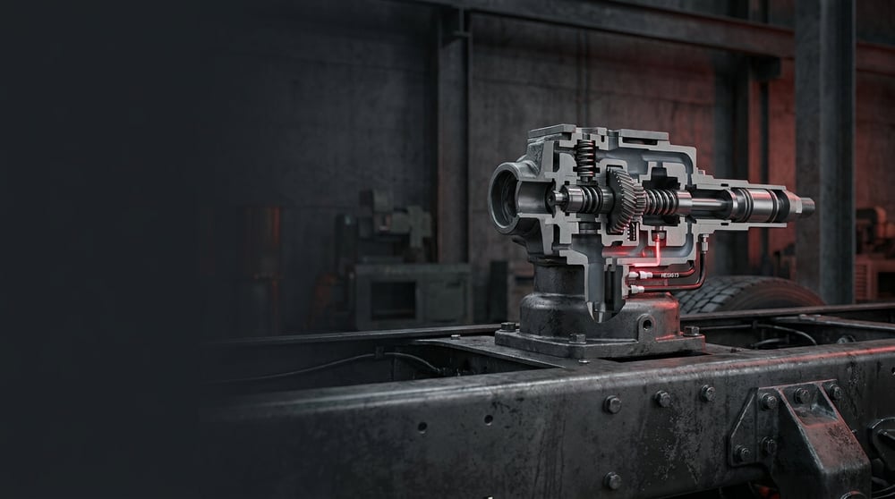
If you have noticed that one side of a tractor unit, bus or trailer with air (bellows) suspension sits lower than the other, that the chassis height keeps shifting between laden and unladen states, or that the ramp/kerb level no longer holds, one of the first components to check is the levelling valve. In truck, tractor, bus and trailer air suspension systems, this valve keeps the chassis at a constant ride height regardless of axle load; it feeds air into the bellows or exhausts air from them. Known in German technical documentation as the Niveauregelventil, it is often referred to in the field as the "height valve", "levelling valve" or "bellows control valve". This guide, compiled for heavy commercial vehicle service technicians, covers the operating logic of the mechanical levelling valve, its common faults, the correct replacement steps and field inspection points.
Editor's note (E-E-A-T): This technical guide was prepared by the VADEN technical team based on field experience with heavy commercial vehicle air suspension systems and OE manufacturer documentation practice. The values here are typical reference ranges; for the exact vehicle-specific ride height, torque and pressure values, always refer to the current OE service manual for the relevant vehicle. Last updated: July 2026.
What Is a Mechanical Levelling Valve? Function and Operating Principle
A mechanical levelling valve is a pneumatic control valve that mechanically senses the distance between the axle and the chassis via a lever and a link rod, and keeps the vehicle's ride height constant regardless of load by feeding air into the air bellows or exhausting air from them.
Its operating principle is based on a "feedback" logic. The valve body is fixed to the chassis; the valve's control lever is connected via a vertical link rod to the axle or the equalising beam. When the vehicle is loaded and the chassis moves closer to the axle (the bellows compress), the lever rotates upward, the intake valve inside opens, and air from the reservoir fills the bellows to raise the chassis back up to the nominal height. When the load is removed and the chassis rises, the lever rotates downward, this time the exhaust valve opens, and the excess air in the bellows is vented to atmosphere; the chassis settles back to the nominal level. When the lever returns to the fully horizontal/neutral position, both valves close and the valve stays in its "balance" (neutral band) position, consuming no air unnecessarily.
Thanks to this continuous correction, the vehicle stays at the same chassis height whether empty or fully laden. Constant ride height is not just a matter of comfort; it is also critical for headlamp aim, driveshaft angle, door/ramp alignment and suspension geometry. Most valves include a delay (damping) band to prevent the system from "pumping" during sudden load changes; the valve does not react to brief road impacts and only engages on a persistent level difference.
- Body: Usually cast from aluminium alloy; houses the supply, delivery (bellows) and exhaust ports.
- Control lever (actuator arm): The mechanical lever that senses the chassis-to-axle distance and connects to the link rod.
- Cam / eccentric mechanism: The internal mechanism that transmits lever movement to the intake and exhaust valves.
- Intake and exhaust valves: The dual-acting valve group that feeds air into the bellows and vents excess air.
- Delay/damping element: The damping that prevents unnecessary correction on short impacts.
- Link rod and joints: The vertical rod with ball joints that connects the valve lever to the axle.
- O-rings and sealing gaskets: Elastomer elements that prevent internal leakage between the ports.
Difference Between Single-Acting and Dual-Acting (Twin-Bellows) Valves
In simple applications, a single-outlet valve feeds both bellows of the axle together. In buses and some tractor units where roll control in corners and finer balance are required, either dual-outlet (twin/duplex) valves that control the right and left bellows separately, or two valves per axle, are used. The twin-bellows arrangement limits the vehicle's lean into corners and corrects the right-left level difference independently. For this reason, the number and layout of ports in valve selection is vehicle-specific.
Damped and Non-Damped Types
Non-damped (instantaneous) valves react to a level difference immediately; they are used in light trailers and some simple applications. Damped valves, on the other hand, wait for a persistent level change before engaging; this reduces air consumption and prevents wearing out the valve and the compressor by constantly filling and emptying the bellows on road impacts. The damped type is mostly preferred in buses and heavy tractor units.
Position in the System and Relation to Manual Lift
The levelling valve is typically mounted near the suspension axle, fixed to the chassis with its lever connected to the axle via a link. If the vehicle has a lift-lower (kneeling) function or a manual load levelling lever, this function is usually provided by a separate control valve or by bypassing the levelling valve; the mechanical levelling valve's job is to maintain automatic, constant height during driving.
Typical Application and Matching
| Application / Segment | Example Use | Key Feature |
|---|---|---|
| Tractor rear axle (air suspension) | Ride height stabilisation | Single/dual outlet, damped type |
| Bus / midibus | Level stabilisation under passenger load + roll control | Separate right-left control (twin valve) |
| Trailer / semi-trailer (air) | Maintaining chassis height under load | Simple, durable single outlet |
| Vehicle with kneeling/lift equipment | Automatic levelling + manual lift | Integrated with an additional control valve |
| EBS/ECAS-equipped vehicle | Electronic level control (backup/supplementary mechanical) | Together with or in place of ECAS |
Part number verification: Although levelling valves look very similar externally, the neutral (balance) band angle, amount of damping, number/layout of ports, lever direction and supply pressure vary by type. The wrong type of valve can cause incorrect ride height, continuous air consumption or one-sided lowering. Before installation, always verify the match using the vehicle's OE part number, port structure, lever side (right/left) and ECAS compatibility if applicable; do not rely on visual similarity.
Fault Symptoms and Diagnosis
Levelling valve faults usually start as "the vehicle is leaning to one side" or "it seems to be constantly losing air". The table below summarises the most common field symptoms together with their possible causes and verification methods.
| Symptom | Possible Cause | Check / Verification |
|---|---|---|
| Vehicle leans to one side / one corner sits constantly low | Valve is not feeding air to the bellows (intake valve stuck) or the link is broken | Manually lift the lever above neutral; watch whether the bellows fill and the chassis rises |
| Vehicle slowly sinks while parked, low in the mornings | Internal valve leakage or the exhaust valve not closing fully | Look for a leak at the exhaust port with soapy foam; rule out bellows and line leaks |
| Chassis higher than it should be, bellows overinflated | Exhaust valve not opening, lever/link adjustment wrong or lever bent | Measure whether the lever is horizontal/neutral at nominal height |
| Continuous air consumption, compressor running excessively | Valve not closing in the balance band, internal leak or link play | With the engine running, listen for continuous air leakage at the exhaust and bellows ports |
| Level does not correct when loaded, vehicle stays low | Supply port restricted, intake valve stuck, damping clogged | Compare the supply pressure and the pressure going to the bellows with a gauge |
| Level corrects too late or over-corrects (pumping) | Damping element faulty, wrong valve type or link adjustment off | Compare the lever angle and valve type (damped/non-damped) with the vehicle specification |
| Level does not hold in the cold, erratic operation | Moisture/water in the system, icing inside the valve | Check the air dryer and reservoir drainage; look for the moisture source |
Function Check with the Lever Test
The fastest field diagnosis is the lever test. Disconnect the link rod from the valve lever. Push and hold the lever upward from neutral: a sound valve should feed air to the bellows and that corner should rise. Push the lever down: the valve should exhaust air from the bellows through the exhaust, and the corner should lower. When the lever is released to neutral, both movements should stop. If no air comes when you lift, the intake side is faulty; if it does not exhaust when you lower, the exhaust side is faulty.
Leak Test and Distinguishing Internal Leakage
With the engine running and the system at nominal pressure, a leak is sought at the exhaust mouth with soapy foam. Continuous air coming from the exhaust while the lever is at neutral indicates that the internal valve (intake valve) is not closing fully, or that there is back-leakage from the bellows side. Caution here: the cause of the vehicle lowering is not always the valve — you first need to confirm that the air bellows, hoses and fittings are not leaking. If the bellows and lines are sound and the lowering continues, the internal leak points to the valve.
Verifying Ride Height and Lever Angle
With the vehicle empty on level ground and at nominal pressure, the chassis-to-axle reference measurement (ride height) is compared against the OE value. In this position the valve lever should be at the neutral angle stated by the manufacturer (usually close to horizontal). If the lever angle is wrong, the vehicle stays either constantly high or low; this is usually a link length or lever adjustment issue, and the valve itself may be sound. For this reason, the link and adjustment must be checked before replacing the valve.
Replacement / Installation Steps
Personal protective equipment (PPE) and safety: Compressed air and a loaded suspension can cause injury. Before starting work, secure the vehicle on level ground, chock it, stop the engine and release the air pressure in the suspension circuit. Make sure the chassis weight rests safely on suitable stands/lifting equipment rather than on the bellows; the chassis can drop suddenly as the bellows deflate. Wear safety glasses and gloves.
- Secure the vehicle: Park on level ground, chock the wheels, switch off the engine and turn the ignition off.
- Record the reference measurement: Before replacement, note the current ride height (chassis-to-axle distance) and lever angle; it will be the reference for adjusting the new valve.
- Release the pressure: Safely vent the suspension circuit/bellows; support the chassis with a stand and verify from the gauge that the pressure has dropped.
- Disconnect the link rod: Remove the link joint that connects the valve lever to the axle; inspect the condition of the joint and rubber bushings, and replace them if damaged.
- Mark the lines: Before disconnecting the supply, bellows (right/left) and exhaust lines, label or photograph them; incorrect connection is the most common mistake.
- Disconnect the air lines: Loosen the fittings with the appropriate wrench; separate the hoses and pipes without forcing, temporarily plugging the port mouths to prevent dirt ingress.
- Remove the old valve: Take the valve out by undoing the bracket/mounting bolts; check the condition of the mounting point on the chassis and the bracket.
- Prepare the mounting surface and bracket: Clean off dirt, rust and old gasket residue; replace the bracket if it is cracked or bent.
- Position the new valve: Fix the valve of the correct type and correct lever side to its bracket so that the port directions suit the vehicle layout; tighten the bolts progressively to the torque specified by the manufacturer.
- Reconnect the lines: Following the labels, connect the supply, bellows and exhaust lines to the correct ports; connect the fittings tightly without overtightening. Make sure the exhaust mouth faces down/free.
- Adjust the link and lever angle: Fill the system to nominal pressure, bring the vehicle to the OE ride height and, in this position, set the link length so that the valve lever is neutral (horizontal), then connect it. Then perform a leak test, and by loading and unloading the vehicle verify that the level corrects properly and stays balanced.
Points to Watch (Common Mistakes)
The most critical mistake — skipping the lever/link adjustment: Fitting the new valve and connecting it without doing the link adjustment causes the vehicle to stay permanently high or low, or to consume air continuously. The valve lever must always be set to the neutral angle specified by the manufacturer while the vehicle is at nominal ride height.
Blaming the lowering on the valve straight away: The most common cause of the vehicle sagging is not always the valve. First, air bellows, hose, fitting and pipe leaks must be ruled out. Replacing the valve before confirming a sound bellows/line usually does not solve the problem.
- Fitting a valve with a different neutral band/damping or the wrong lever side by trusting visual similarity — incorrect level and pumping.
- Connecting the link joint/bushings with play or at the wrong length — vibratory, late or incorrect correction.
- The exhaust mouth facing up or being blocked — water/dirt accumulation and freezing in winter.
- Working without releasing the pressure and supporting the chassis — sudden chassis drop, serious injury risk.
- Reusing old, hardened O-rings and gaskets — internal leakage.
- Skipping the laden/unladen level and leak test after installation — level loss on the road or one-sided leaning.
- Replacing the valve without solving the air dryer/moisture problem — the new valve is soon affected too.
Technical Values and Control Points
The values below are typical / general reference ranges for heavy commercial vehicle air suspension systems. They vary by vehicle and valve type; for exact values the OE service manual is authoritative.
| Parameter | Typical Reference Range | Note |
|---|---|---|
| System supply pressure | ~8–12.5 bar (≈116–181 psi) | Varies by vehicle and circuit |
| Bellows (suspension) working pressure | Variable with load, typically ~0.5–8 bar | Depending on unladen/laden state |
| Neutral (balance) band angle | At nominal height the lever ≈ horizontal (±a few degrees dead band) | OE specification is authoritative |
| Permitted internal leakage | In practice "zero" is targeted; measurable leakage = fault | No continuous bubbling in the soap test |
| Operating temperature range | ~ −40 °C to +80 °C | Elastomer and freezing limit |
| Level correction behaviour | Gradual and balanced correction on a persistent load change | The damped type does not react to short impacts |
Connection torques also vary by type and bolt size; the values below are only a general reference.
| Connection | Typical Torque Range | Note |
|---|---|---|
| Body/bracket mounting bolt (M8) | ~20–30 Nm | Tighten progressively and crosswise |
| Body/bracket mounting bolt (M10) | ~40–55 Nm | OE value is authoritative |
| Lever clamp/pinch bolt | Per manufacturer specification (typically ~8–15 Nm) | Tighten after adjusting the lever angle |
| Air line fitting | Per manufacturer specification | Do not overtighten; do not strip the thread |
Field tip: Before replacing the levelling valve, check the link joints, rubber bushings and lever angle. A significant portion of "vehicle leaning" complaints stem from a link rod with play or a bent one, a leaking bellows or a poorly adjusted lever; the valve is often innocent.
- With the vehicle empty and at nominal pressure, is the ride height at the OE value?
- In this position, is the valve lever at the neutral (horizontal) angle?
- Are the link joints and bushings free of play and is the rod the correct length?
- When the lever is pushed up does the bellows fill, and when pushed down does it exhaust?
- Is the exhaust mouth free, facing down, and free of air leakage at neutral?
- Is the right-left level difference within OE tolerance (in a twin-bellows/twin-valve arrangement)?
Maintenance and Service Life
The mechanical levelling valve is long-lasting when fed with clean, dry air and when its mechanical connections are kept sound. Its main enemies are moisture, dirt and mechanical wear: freezing, bellows/link impacts and vibration wear out the valve's lever, joint and internal valves. In periodic maintenance, the valve should be assessed not as a separate component but as part of the entire air suspension and air preparation circuit.
- Replace the air dryer cartridge within the manufacturer's interval; stop moisture at its source.
- Drain the air reservoirs periodically (especially before winter), emptying accumulated water and oil.
- Regularly check the link rod joints, rubber bushings and lever for play/cracks.
- Keep the exhaust mouth and any silencer clean, open and facing down.
- In periodic maintenance, measure the unladen/laden ride height and the right-left balance.
- Rather than forcing a symptomatic valve, since level and suspension safety are critical, prefer to replace it complete if the type is suitable.
A healthy levelling valve usually operates trouble-free throughout the vehicle's long service life; however, in moist systems, with connections that have play, or in vehicles whose maintenance is neglected, its life is shortened. Timely intervention on level problems both preserves ride comfort and headlamp/ramp alignment and prevents the tyre wear and suspension strain caused by one-sided leaning.
Frequently Asked Questions
What does a levelling valve do?
In a vehicle with air suspension, it keeps the chassis at a constant ride height regardless of load. It senses the axle-to-chassis distance with a lever; when necessary it feeds air into the bellows or exhausts air from them to correct the level.
What are the symptoms of a levelling valve fault?
The most common are: the vehicle leaning to one side, slowly sinking while parked, the chassis staying higher than it should, continuous air consumption, and the level not correcting when loaded.
If the vehicle leans to one side, is the valve always to blame?
No. The cause of leaning or sagging is often a leaking air bellows, a hose/fitting leak, a link rod with play or a wrong lever adjustment. Before replacing the valve, the bellows, lines and link must be checked.
Is adjustment required when the levelling valve is replaced?
Yes. After the new valve is fitted, the vehicle must be brought to the OE ride height and the valve lever set to the neutral (horizontal) position. If this adjustment is not made, the vehicle can stay permanently high/low or consume air continuously.
What is the difference between a mechanical levelling valve and an electronic (ECAS) system?
A mechanical valve corrects the level entirely with a mechanical lever and pneumatic valves. Electronic level control systems such as ECAS do the same job electronically with a height sensor, an electronic control unit and solenoid valves; they allow additional functions such as lift-lower. The part numbers and installation of the two differ from each other.
The valve is continuously losing air, what should I do?
Continuous air coming from the exhaust mouth while the lever is at neutral indicates the internal valve is not closing fully; first bellows and line leaks are ruled out, and if the problem is confirmed to be in the valve, the valve is replaced. A continuous leak causes both air loss and unnecessary running of the compressor.
What happens if the wrong type of levelling valve is fitted?
A valve with a different neutral band, damping value, port layout or wrong lever side causes incorrect ride height, right-left imbalance, continuous correction (pumping) and excessive air consumption. For this reason, matching must always be done with the OE part number and lever direction suited to the vehicle.
Which brands is the levelling valve compatible with?
VADEN levelling valve products are designed to be functionally compatible with the OE types of common heavy commercial vehicle air suspension systems (e.g. Knorr-Bremse, Wabco/ZF, Bendix type/equivalent). For correct matching, the port structure, lever side and OE reference number should be checked.
The mechanical levelling valve is a critical component that directly determines the ride height, balance and comfort of a heavy commercial vehicle's air suspension system. With correct diagnosis, correct type selection, careful installation and especially the correct lever/link adjustment, both level safety and vehicle efficiency are preserved. The VADEN ORIGINAL Mechanical Levelling Valve product family is developed for heavy commercial vehicle applications with an OE-compatible port structure, durable sealing elements and a consistent balance band; by verifying the correct reference and lever direction for your vehicle, you can achieve safe and long-lasting suspension performance.