Air Brake Systems

Air Brake System Diagram for Trucks, Buses and Trailers | VADEN ORIGINAL
Temmuz 10, 2026
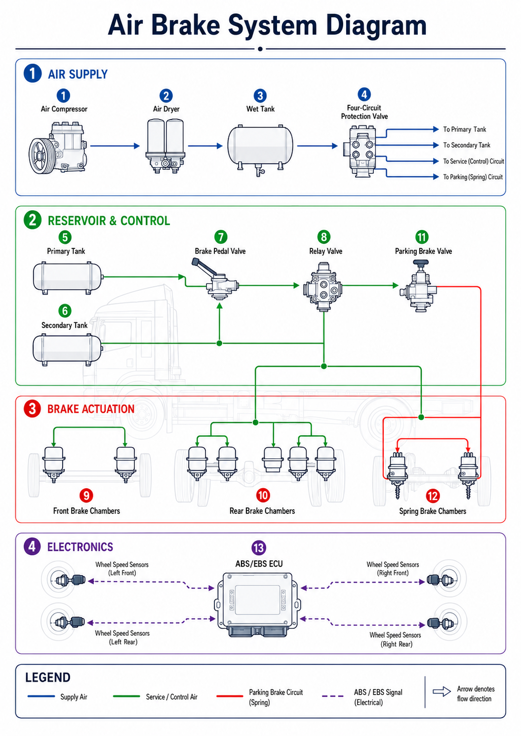
This air brake system diagram maps the complete compressed-air braking circuit of a heavy commercial vehicle — truck, bus or trailer — from the moment air is generated to the instant each wheel is braked. Unlike a passenger car, these vehicles use compressed air rather than hydraulic fluid as the working medium, which is why every reservoir, valve and brake chamber has to be laid out clearly. The labelled illustration groups the system into four functional sections so truck technicians, fleet buyers and students can follow the airflow and understand how each component depends on the next.
⬇ Download the full Air Brake System Technical Guide (PDF)
Section one, Air Supply, is where compressed air is produced and conditioned: the engine-driven compressor feeds the air dryer, which removes moisture and oil before the air reaches the wet tank; from there the four-circuit protection valve divides the supply into independent circuits and seals off any circuit that loses pressure. Section two, Reservoir and Control, stores and meters that air — the primary and secondary tanks feed the two service circuits, the brake pedal (foot) valve delivers air on demand, the relay valve shortens response time at the rear axle, and the parking brake valve commands the spring brakes.
Section three, Brake Actuation, is where air pressure becomes mechanical braking force through the front, rear and spring brake chambers; the spring (combination) chambers also provide the parking and emergency brake. Section four, Electronics, overlays the pneumatic system with an ABS/EBS ECU and wheel-speed sensors that monitor each wheel and modulate pressure to prevent lock-up and shorten stopping distances. Read together, the four sections show how VADEN ORIGINAL braking components work as one coordinated safety system.
Related product categories: Air Brake Compressors · Air Dryer Valve · Relay Valve · Quick Release Valve · Brake Cylinder
Frequently Asked Questions
What does an air brake system diagram show?
It shows the full compressed-air braking circuit of a heavy vehicle and how air flows from the compressor, through the air dryer, reservoirs and control valves, to the brake chambers at each wheel, plus the ABS/EBS electronics. In this diagram the components are grouped into four sections: air supply, reservoir and control, brake actuation, and electronics.
How does a truck air brake system work?
The compressor charges the reservoirs with compressed air through the air dryer, which keeps the system clean and dry. When the driver presses the brake pedal, the foot valve meters air to the front and rear brake chambers; inside each chamber a diaphragm pushes the pushrod and slack adjuster to apply the brake. Releasing the pedal exhausts the air and the brakes retract.
What is the four-circuit protection valve for?
It splits the air coming from the wet tank into separate, isolated circuits — typically primary service, secondary service, parking, and auxiliary or trailer supply. If one circuit develops a leak or fails, the valve protects the remaining circuits so the vehicle keeps its braking capability. This built-in redundancy is a core safety requirement for commercial vehicles.
What is the difference between a service brake chamber and a spring brake chamber?
A service (single-diaphragm) brake chamber applies the brake only when air pressure is supplied and is typically fitted on the steer/front axle. A spring (combination) brake chamber adds a powerful internal spring: air pressure holds the spring compressed to keep the brake released, and when pressure drops — for parking or in a failure — the spring applies the brake automatically. These are used on the drive/rear axle.
What do ABS, EBS and ALB do in an air brake system?
Wheel-speed sensors feed the ABS/EBS ECU, which modulates brake pressure to stop the wheels locking under hard braking, keeping the vehicle stable and steerable. EBS (electronic braking system) adds faster, brake-by-wire control with a pneumatic backup for redundancy. ALB (automatic load-sensing brake force regulation) adjusts braking effort to the vehicle's load, so an empty and a fully laden truck both brake safely.
Shop this part: Brake System
Share
Related Articles
Air Brake Systems
Air Brake Compressor: Faults, Replacement & Maintenance Guide
Air Brake Systems
Air Dryer: Faults, Replacement & Maintenance Guide
Air Brake Systems