AIR BRAKE SYSTEMS IN HEAVY COMMERCIAL VEHICLES: WORKING PRINCIPLE, COMPONENT GLOSSARY AND COMPREHENSIVE FAULT-FINDING GUIDE
How truck and trailer air brake systems work, a full component glossary and expert fixes for the 10 most common air brake faults. VADEN ORIGINAL technical guide.
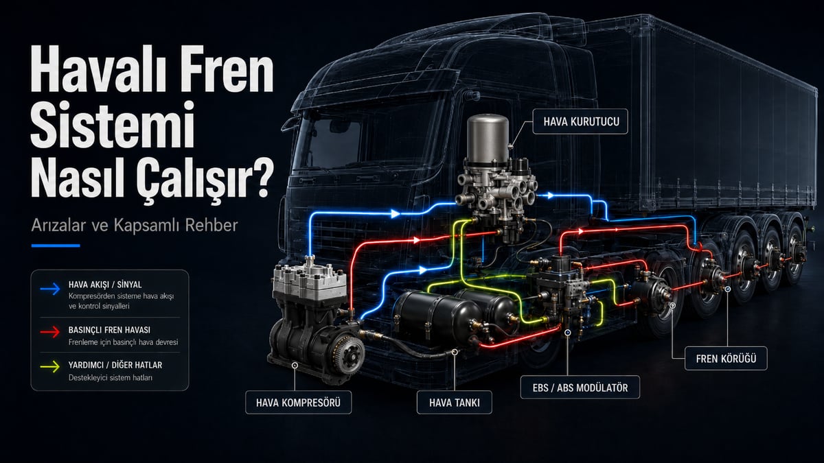
AIR BRAKE SYSTEMS IN HEAVY COMMERCIAL VEHICLES: WORKING PRINCIPLE, COMPONENT GLOSSARY AND COMPREHENSIVE FAULT-FINDING GUIDE
Enabling the enormous masses of heavy commercial vehicles (trucks, articulated lorries, buses and tractor units) to stop safely is not possible with the hydraulic fluids used in standard passenger cars. Instead, an unlimited and environmentally friendly resource - atmospheric air - is used. Air brake systems are flawless pneumatic and electromechanical systems that work on the principle of compressing, conditioning and storing air, then routing it to the wheels within milliseconds to convert it into mechanical force.
In this comprehensive guide you will find how the system works step by step, exactly what each sub-component does, the professional solutions to be applied in the event of a fault, and the answers to every question that may come to mind.
1. HOW DOES AN AIR BRAKE SYSTEM WORK? (THE 5-STAGE OPERATING CYCLE)
Rather than a structure that simply pumps air at random, the system consists of 5 main stages bound by strict thermodynamic and mechanical rules.
Stage 1: Generation (Compressing the Air)
-
What Is It?: This is carried out by the Air Brake Compressor, the heart of the system. The compressor draws its power directly from the vehicle's engine (from the crankshaft or the gear train).
-
How Does It Work?: Think of it like a piston engine. As the vehicle engine runs, the compressor's piston moves up and down. As the piston descends (intake stroke), it draws in atmospheric air from outside the vehicle or air coming from the turbocharger through the intake valve. As the piston rises (compression stroke), it compresses this air inside the cylinder.
-
Physical Detail: Because the molecules of the compressed air move closer together, the air heats up considerably in accordance with the laws of thermodynamics (it can reach up to 200°C - 250°C) and its pressure reaches the 8.5 to 12.5 bar range. During this process, to prevent itself from overheating, the compressor circulates the vehicle's engine coolant (antifreeze) through its own body.
Stage 2: Conditioning (Cleaning, Cooling and Drying)
-
What Is It?: This is the removal of moisture (water vapour) and oil particles from the compressed air, which are harmful to the system. This process is performed by the Air Processing Unit (APU/E-APU) and the Air Dryer / Unloader Valve.
-
How Does It Work?: The 200°C air leaving the compressor passes through a steel cooling pipe (coil) and is brought below 60°C. It then enters the filter (cartridge) of the air processing unit. Inside this filter are "silica gel" granules that absorb water like a sponge. As the air passes between these granules, the moisture within it is trapped. In addition, the fine layer at the bottom of the filter captures the micro oil vapour that may leak from the compressor.
-
Why Is It Important?: If this process is not carried out, the water in the system freezes at -20°C in winter and bursts the valves, or in summer it rusts the metals and locks the pneumatic actuators.
Stage 3: Storage and Circuit Separation (Safe Reserve)
-
What Is It?: This is the holding of the dried, clean air ready in pressurised tanks (air reservoirs) until braking occurs, and its separation into safety circuits by the Four-Circuit Protection Valve.
-
How Does It Work?: The system does not fill a single large tank with air. If it did, a small hose burst would disable all of the vehicle's brakes. The four-circuit protection valve divides the air into 4 or more independent circuits:
-
Circuit: Rear Axle Service Brake
-
Circuit: Front Axle Service Brake
-
Circuit: Parking (Emergency) Brake and Trailer Supply
-
Circuit: Air Suspension and Accessories (door, horn)
-
-
Safety Logic: Pressure priority always lies with circuits 1 and 2. For example, if the suspension air bellows bursts (circuit 4), the four-circuit valve mechanically closes that line, ensuring the remaining air stays in the tanks for the brakes.
Stage 4: Distribution and Signal Control (Routing)
-
What Is It?: This is the mechanical or electronic transmission of the driver's braking demand to the valves. The main components are the Foot Brake Valve (Brake Master Cylinder) and the EBS Brake Module.
-
How Does It Work?: When the driver presses the brake, they do not open the air line running directly to the wheels with their own foot. The force applied to the pedal creates a signal. In conventional systems, the pedal opens a valve at the rear, sending a small "pilot air pressure" (signal). In modern systems, the EBS Brake Signal Transmitter beneath the pedal converts the foot movement into an electrical signal and transmits it to the EBS control module. The EBS module calculates speed, steering angle and load within milliseconds and issues commands to the EBS Relay Valve and the modulators.
Stage 5: Pneumatic Actuators (Conversion into Mechanical Force)
-
What Is It?: This is the arrival of the distributed high-pressure air at the Brake Chambers at the wheel centres, pressing the brake pads against the disc.
-
How Does It Work?: The 10 bar air entering the brake chamber forcefully inflates a rubber diaphragm inside (like a thick balloon). This inflation movement presses the push rod (attached to the diaphragm) forward. The push rod rotates the brake caliper mechanism and presses the pads against the brake disc with extraordinary force, and friction begins.
-
Release (Releasing the Brake): When the driver lifts their foot off the pedal, the Quick Release Valve comes into play. Instead of the air returning along the long route it came, it is instantly exhausted to the atmosphere through this valve with a "hiss" and the wheel is freed.
2. AIR BRAKE SYSTEM COMPONENT GLOSSARY
A functional grouping of the spare parts that make up the system, each of which must be manufactured to OEM standards:
A. ABS and EBS Electronic Control Group
-
EBS Brake Module: The main computer of the system. By analysing the load and road conditions, it manages the bar value to be sent to the wheels.
-
ABS Electronic Control Unit (ECU): The main brain that detects wheel lock-up and applies pneumatic intervention.
-
ABS Sensor: Continuously measures the rotational speed of the wheel hub and transmits the data to the ECU.
-
EBS Brake Signal Transmitter: Reads the mechanical foot pressure on the brake pedal and converts it into a digital command.
-
EBS Modulator / EBS Axle Modulator / EBS Dual-Channel Modulator: Electromechanical actuating elements that open and close the valves according to the electronic signals coming from the brain.
-
EBS Trailer Modulator & EBS Trailer Control Valve: Equalises the brake pressures of the tractor and trailer, preventing jackknifing (folding).
-
ABS Relay Valve / ABS Dual Relay Valve / EBS Relay Valve / Relay Valve: Relays that, with a small trigger signal, rapidly transfer the large mass of air in the tanks to the wheels.
B. Air Preparation and Distribution Group
-
Air Processing Unit: The main manifold in which the dryer, oil separator and pressure regulator are integrated.
-
Air Dryer / Unloader Valve: The valve that unloads the compressor (cut-out) when the system pressure reaches its limit and exhausts the excess air after drying it.
-
Four-Circuit Protection Valve / Multi-Circuit Protection Valve: Ensures the safety-prioritised distribution of air to the tanks over 4 or more circuits.
-
Distributor Valve: Manages the flow at the branches in the air lines.
-
Pressure Limiting Valve: Limits the ceiling so that sensitive components such as the trailer are not damaged by high pressure (excess bar).
C. Control, Ride and Suspension Valves
-
Brake Master Cylinder / Foot Brake Valve: The valve that converts the driver's foot input directly into air pressure.
-
Trailer Control Valve: The valve that transmits a pneumatic command to the trailer when the tractor brakes.
-
ALB Load Sensing Valve: Reads whether the vehicle is empty or laden from the air bellows pressure and proportions the rear brake force according to the amount of load.
-
Trailer Levelling Valve: Feeds air to the air suspension to keep the trailer chassis parallel to the ground despite the load.
-
Axle Lift Valve: The valve that raises the axle into the air when the vehicle is empty to prevent tyre wear and save fuel.
-
Door Control Valve: Manages the pneumatic door cylinders on buses.
D. Pneumatic Actuators, Safety and Connection Elements
-
Brake Chamber: The main cylinder in which the pressurised air is converted into a mechanical pressing force that pushes the brake pad.
-
Park and Release Valve: Manages the emergency brake (handbrake). When pulled, it exhausts the air from the system, allowing the springs to mechanically lock.
-
Emergency Valve: The safety element that automatically locks the trailer brakes when the tractor-trailer air hose is severed.
-
Overload / Pressure Relief Valve: Acts as a bypass when the pressure rises excessively.
-
Air Exhaust Valve / Exhaust Valve / Quick Release Valve: Exhausts the air to the atmosphere when the brake is released, immediately freeing the wheel.
-
Check Valve: Allows the air to flow in one direction only in the lines and prevents back-leakage.
-
Connection Equipment / Fittings: The nipples that connect the polyamide hoses to the valves in a leak-tight manner.
-
Brake Dust Shield: The armour that protects the caliper mechanism from mud, stones and road debris.
3. THE 10 MOST COMMON AIR BRAKE FAULTS AND THEIR SOLUTIONS
Trial and error is not an option in heavy vehicle repair. Below are the engineering solutions to the pneumatic and electromechanical faults most frequently encountered in the field and in workshops:
1. Brakes Not Releasing (Binding and Overheating Problem)
-
Symptom: The pads continue to rub against the disc even though the foot has been lifted off the pedal, causing overheating and a burning smell.
-
Root Cause: The exhaust port of the Quick Release Valve may be blocked by oil/mud. The air's inability to exhaust prevents the diaphragm from retracting.
-
Remedy: The exhaust ports of the relevant valves must be cleaned, or the valve must be overhauled with a repair kit (diaphragm/O-ring).
2. The System Building Air Pressure Too Slowly
-
Symptom: It takes minutes for the pressure gauges on the dashboard to reach the 8.5 bar level after the vehicle is started.
-
Root Cause: There is excessive carbon build-up on the cylinder head (valve plate) of the Air Brake Compressor, or there is a loss of "compression" because the rings are worn. Alternatively, there may be a large fitting leak.
-
Remedy: After a leak check, a pressure gauge is fitted to the compressor outlet and the flow rate is measured. The compressor cylinder head or the complete compressor is renewed with a product manufactured to OEM standards.
3. Trailer Swing (The Trailer Pushing the Tractor)
-
Symptom: On a slippery surface or under sudden braking, the trailer comes round from the rear and folds the tractor (jackknifing).
-
Root Cause: Loss of brake synchronisation between the tractor and the trailer. The Trailer Control Valve may be delayed in transmitting pressure.
-
Remedy: A "Tractor-Trailer Sync" (synchronisation) test is carried out with a diagnostic device. The outlet pressures of the yellow and red couplings are calibrated.
4. Parking (Emergency) Brake Not Releasing
-
Symptom: Even though the air tanks are full, the vehicle does not move when the handbrake valve is lowered (the wheels remain locked).
-
Root Cause: On air brakes, the handbrake holds by "exhausting air". If the Park and Release Valve cannot send air to the rear emergency (spring brake) chambers, or if the enormous spring inside the chamber has broken, the wheel will not release.
-
Remedy: The park valve outlet pressure (bar) is measured. If the pressure is correct, the faulty brake chamber is released using its manual wind-off bolt and the part is renewed.
5. Pneumatic Delay at the Brake Pedal (Sponginess)
-
Symptom: A momentary gap of a second is felt between pressing the brake and braking actually taking place.
-
Root Cause: The rubber diaphragms or O-rings inside the EBS Relay Valve have hardened over time (thermal fatigue), losing their opening-closing speed.
-
Remedy: The relay valves are renewed with genuine repair kits, and the reaction time (in milliseconds) is measured with a diagnostic tool.
6. Oil Discharge from the Dryer Valve
-
Symptom: Black, foamy engine oil is discharged from the lower exhaust of the Air Processing Unit (APU).
-
Root Cause: The compressor is drawing engine oil from the crankcase and pushing it into the air line. The compressor's oil control rings have lost their function.
-
Remedy: Merely changing the filter will not solve the problem. The compressor must be overhauled urgently, the polyamide lines in the system flushed, and finally the dryer cartridge replaced.
7. Valves Freezing in the Winter Months
-
Symptom: When the air temperature drops below 0°C, the brake pedal hardens or the vehicle exhausts all its air and locks itself.
-
Root Cause: As a result of the Air Dryer / Unloader Valve filter not being changed in time, the moisture remaining in the system freezes in the valve channels.
-
Remedy: NEVER apply a flame/blowtorch to frozen valves (the internal seals will melt). They are thawed with warm air, water is drained from the manual moisture drain cocks (at the bottom of the tank) and a new filter is fitted.
8. Compressor Not Cutting Out (Continuous Puff-Puff Sound)
-
Symptom: Even when the maximum pressure of 10-12 bar is reached, the system continuously exhausts the air from the unloader valve.
-
Root Cause: The pressure limiting/regulator valve is unable to send the "stop production" signal to the compressor.
-
Remedy: The regulator setting of the unloader valve is checked. It is replaced if necessary; otherwise the compressor runs continuously at full load and quickly disintegrates from excessive heat.
9. Air Pressure Dropping After the Ignition Is Switched Off
-
Symptom: The air tanks of a vehicle parked overnight are completely at zero in the morning.
-
Root Cause: A micro-level pneumatic leak from the diaphragm of the Four-Circuit Protection Valve, from the check valves, or from the connection fittings.
-
Remedy: With the system fully charged, all valve exhausts and pneumatic nipples are checked in a quiet environment with foam spray (leak detection fluid).
10. ABS/EBS Warning Lamps Constantly Illuminated
-
Symptom: The red or yellow EBS/ABS fault icons on the instrument panel do not go out.
-
Root Cause: This is usually not a hardware issue but an electrical one. The cable of the ABS Sensor has snapped, the sensor has moved away from the reluctor ring, or the EBS brain has oxidised.
-
Remedy: The Ohm resistance of the sensor is measured with a multimeter. The reluctor ring (pole wheel) on the hub is cleaned with rust remover. The sensor gap is adjusted to the factory value.
Shop this part: Brake System
Tags
Frequently Asked Questions
- How many stages does an air brake system work in?
- An air brake system works in a cycle made up of 5 main stages: generating the air by compressing it in the compressor, conditioning it in the air processing unit (cleaning, cooling and drying), storing and separating it into circuits with the four-circuit protection valve, distribution and signal control via the foot brake valve or the EBS module, and finally the conversion into mechanical force by the pneumatic actuators in the brake chambers. These 5 stages are flawlessly linked together with parts manufactured to VADEN ORIGINAL quality.
- Why does the air in the air brake compressor heat up so much, and what is its pressure?
- The compressor moves its piston using power drawn from the vehicle's engine and compresses the air inside the cylinder; as the molecules move closer together, the laws of thermodynamics cause the air to heat up to 200-250 C and its pressure to reach the 8.5-12.5 bar range. During this process, to prevent itself from overheating, the compressor circulates the vehicle's engine coolant (antifreeze) through its own body.
- Why is the air processing unit (dryer) necessary, and what happens without it?
- The hot air leaving the compressor is first passed through a cooling pipe and brought below 60 C, after which the silica gel granules in the air processing unit trap the moisture in the air and dry it, while also capturing micro oil vapour. If this conditioning is not carried out, the water in the system can freeze at -20 C in winter and burst the valves, or in summer it can rust the metals and lock the pneumatic actuators.
- What does the four-circuit protection valve do, and why is a single large tank not used?
- The four-circuit protection valve divides the dried air into at least 4 independent circuits: the rear axle service brake, the front axle service brake, the parking (emergency) brake with trailer supply, and the air suspension/accessories. This way, if the suspension bellows bursts, for example, the valve mechanically closes off that line so the remaining air stays in the brake circuits; if a single large tank were used, a small hose burst would disable all the brakes.
- How is air transmitted to the wheels when the brake pedal is pressed?
- When the driver presses the brake, the pedal does not open the air line running directly to the wheels; in conventional systems the pedal opens a valve to send a pilot air pressure signal, while in modern systems the EBS brake signal transmitter converts the foot movement into an electrical signal and passes it to the EBS control module. The EBS module calculates speed, steering angle and load within milliseconds and sends up to 10 bar of air to the brake chambers; this air inflates the internal diaphragm and pushes the push rod, pressing the pads against the disc.
Related Articles
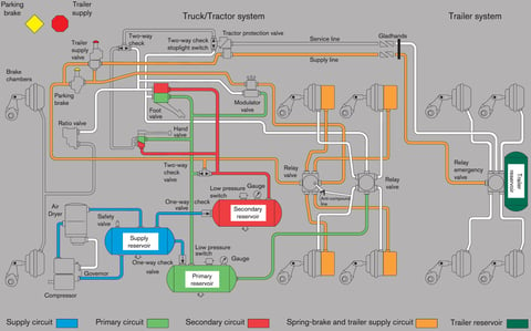
Air Brake Systems: Working Principle, Maintenance and Safety Tips
Detailed guide to air brake systems for heavy-duty vehicles. Learn about the working principle, components, advantages, disadvantages, maintenance and safety tips.

Brake Safety on Long Descents: What Is Brake Fade, and How Do You Use the Retarder and Engine Brake?
Learn what brake fade is, how retarders and engine brakes work, and the correct technique for safe air brake management on long descents.
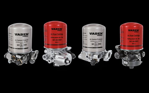
The Air Dryer: The Hidden Hero of Heavy Vehicle Air Systems (Truck Air Dryer)
Delve into the essential air dryer component in commercial vehicle air brake systems. Learn what it does, how it works, common failures and symptoms, and why its regular maintenance is crucial for preventing costly damage and ensuring safety.


