Compressor Repair and Gasket Kit: Faults, Replacement, Care
A field guide to diagnosing air compressor gasket failure, choosing the right kit scope, preparing surfaces, torquing correctly and extending seal life.
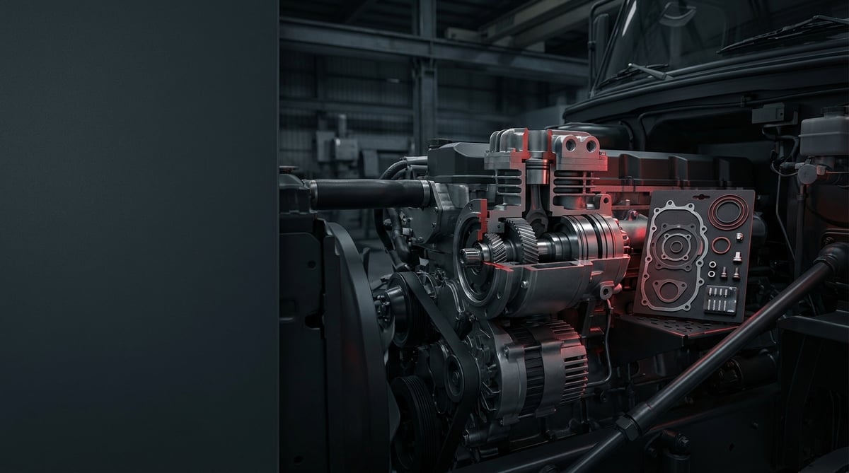
The air brake compressor is the component that works hardest all day long on a heavy commercial vehicle, yet is talked about the least. When oily air keeps coming out of the air dryer, when system pressure no longer builds as quickly as it used to, or when a dried mixture of oil and carbon has collected around the compressor head, the first reflex in most workshops is to replace the complete compressor. In practice, however, the most common picture in the field is a compressor whose housing and crank assembly are still sound, but whose gaskets, valve plate and sealing elements have simply reached the end of their service life. This guide explains, from a workshop foreman's point of view, what a compressor repair and gasket kit is, how to read the fault, what removal and fitting discipline the job demands, and which maintenance habits extend the life of the kit.
What Is a Compressor Repair and Gasket Kit? Function and Working Principle
The Compressor Repair and Gasket Kit is the service set used when a heavy commercial vehicle air brake compressor is dismantled and refurbished; it consists of cylinder head and housing gaskets, valve plate gaskets, O-rings, sealing rings and, depending on type, the valve plate, spring and unloader sealing elements. Heavy commercial compressors typically operate at a cut-out pressure of 8-12.5 bar, and in most applications the gasket kit is renewed within the 250,000-400,000 km band.
The compressor repair and gasket kit is known by several names in catalogues and in the field: compressor gasket kit, compressor repair kit, compressor overhaul set, valve plate kit and, for the narrower versions, head gasket set. They are all members of the same product family with different scopes; the scope may change, but the selection criteria stay the same: compressor type, the OE number on the housing, and the cylinder or head configuration.
To understand the working principle you have to look at what the compressor actually does. Driven by the engine, the compressor draws in air with its piston, compresses it and delivers it through the intake and delivery valves on the valve plate to the air dryer and from there to the air tanks. The pressure regulator unloads the compressor once cut-out pressure is reached; when tank pressure drops, the compressor goes back into load. This cycle repeats every second the vehicle is running, and on every cycle the gaskets between the valve plate and the head are exposed both to pressure pulses and to the heat generated by compression.
This is exactly where the criticality of the part begins. At the moment of compression the air temperature on the delivery side can reach several hundred degrees at the compressor head, while engine coolant flows just a few centimetres away. In other words, the same gasket face has to separate very hot pressurised air from coolant across a very short distance. That is why the picture that emerges when a gasket becomes fatigued is not uniform: sometimes it appears as an external air leak, sometimes as oil passing into the crankcase side, and sometimes as coolant seeping from the water jacket into the air side.
What does the kit typically contain?
- Cylinder head gasket: seals between the head and the valve plate so that the air and coolant passages remain separated.
- Valve plate (intermediate plate) gasket: sits between the plate and the block; it is the basis of the intake and delivery separation.
- Housing / crankcase gasket: used between the compressor housing and the engine mounting face or the bottom cover.
- O-rings: in the air, oil and coolant passages; size and material class are application specific.
- Crankshaft / shaft seal: provides oil sealing on the drive side.
- Valve plate, valve reeds and springs: included in wide-scope repair kits.
- Unloader sealing elements: plunger seal, spring and O-ring set.
- Piston ring set and bearing components: found only in full overhaul sets.
- Sealing washers and locking elements: single-use items are renewed at every removal.
Gasket kit, repair kit or a complete compressor?
The decision is made on the basis of three pieces of data: the condition of the housing, cylinder and piston wear, and the type of fault. If there is only a gasket-related air or oil leak, the cylinder bore is within tolerance and crankshaft clearance is normal, a gasket kit is sufficient. If the valve reeds are fatigued and pitting has started on the plate face, a wide-scope repair kit is needed. If there is visible scoring or ovality in the cylinder, or crankshaft and connecting rod clearance, the economically correct decision is a complete compressor. This distinction must be made by measurement, not by eye; the most common mistake in the field is fitting a new gasket kit to a worn housing and living through the same fault again a few months later.
Standards and normative framework
Although the compressor repair and gasket kit may not look like a safety part on its own, it is part of the air supply that directly determines the braking performance of the vehicle. On heavy commercial vehicles the brake system as a whole is assessed under ECE R13; for the air generation and storage side of the system EN 286-2 (air tanks for road vehicles) and, for the cleanliness classification of compressed air, ISO 8573-1 are widely used references. For sealing elements, O-ring size and tolerance families are generally based on the logic of ISO 3601. These standards do not give a direct part number for a product; which standard applies in which scope, and which class the part falls into, must be verified from the relevant OE catalogue.
| Compressor type | Common application example | Key items in the kit | Service note |
|---|---|---|---|
| Single cylinder, air cooled | Light and medium commercial, trailer and construction machinery applications | Head gasket, valve plate gasket, O-ring set | Narrow scope; flatness of the head face is critical |
| Single cylinder, water cooled | Heavy commercial tractor unit and truck applications | Head and plate gasket, coolant passage O-rings, shaft seal | If the water-to-air separation fails, coolant leakage appears |
| Twin cylinder, water cooled | High air consumption tractor units, buses, crane-equipped vehicles | Twin head gasket set, valve reed and spring, unloader set | The two heads are torqued in sequence and in stages |
| Unloader controlled compressor | Modern Euro 5 / Euro 6 generation vehicles | Unloader plunger seal, spring, control O-rings | If unloading leaks, the compressor stays permanently in load |
| Full overhaul (major overhaul) set | High mileage compressor whose housing is still within tolerance | All gaskets plus piston rings, bearings and valve group | Not chosen before the cylinder dimension is verified |
How do you tell a Compressor Repair and Gasket Kit has failed?
Compressor repair and gasket kit failures do not announce themselves as "the gasket has blown"; they show up as slow pressure build-up, oil coming out of the dryer, coolant loss or wetness around the compressor. The table below matches field symptoms with their likely causes and the verification method.
| Symptom | Likely cause | Check / verification |
|---|---|---|
| Air pressure builds very slowly, the compressor runs continuously | Valve plate gasket is leaking, valve reed is fatigued or the delivery side has an internal leak | Measuring the time taken to reach cut-out pressure from empty tanks; verifying that there is no external leak in the system |
| A constant oily, black mixture comes out of the air dryer | Piston ring and housing sealing has weakened, crankcase oil is passing to the delivery side | Collecting the dryer purge into a clean container and observing the oil content; checking the age of the dryer cartridge |
| Carbon and oil mixture building up around the compressor head | The head gasket is not seating under pressure pulses, there is torque loss or a surface defect | Cleaning the area and tracing the leak with soapy water while the engine runs; torque check of the head bolts |
| Coolant level is dropping with no visible external leak | The coolant passage O-ring or the water-to-air separation of the head gasket has failed | Pressure testing the cooling system; looking for coolant traces and smell in the compressor purge |
| The compressor head runs unusually hot | Internal circulation on the delivery side, a restricted delivery line or continuous operation under load | Comparing head and outlet line temperatures with a non-contact thermometer; checking the line for restriction |
| Engine crankcase oil level rises or crankcase pressure increases | Passage between the housing/crankcase gasket and the shaft seal; unloader sealing is leaking | Monitoring the oil level; verifying that the compressor oil return line is clear |
| The compressor does not unload and stays in load after cut-out pressure | The unloader plunger seal is leaking, the control O-ring is fatigued | Monitoring control line pressure at the moment of cut-out; verifying the pressure regulator outlet separately |
| Oil leakage and oily dust sludge on the compressor drive side | The crankshaft/shaft seal has reached the end of its life or was damaged during fitting | Cleaning the area around the drive pulley and inspecting it again after a short run |
| Moisture in the brake system, water collecting in the tanks | Very hot air from an overheating compressor is overloading the dryer | Checking for water at the tank drain valves; measuring how long the compressor stays in load |
Diagnosis with the build-up time test
The most practical way to measure compressor efficiency is the build-up time test. The system is fully drained, it is confirmed that there is no external leak, the engine is held at a defined speed and the time taken for the tanks to reach cut-out pressure is measured with a stopwatch. If the time is significantly above the figure given in the service manual for that vehicle, the internal efficiency of the compressor has dropped. The most critical precondition for this test is to establish beyond doubt that there is no external air leak before measuring; a leaking dryer or a loose fitting will make a sound compressor look guilty.
Oil carry-over or a tired dryer?
Oil coming out of the dryer does not on its own condemn the compressor. The same picture appears when the dryer cartridge has reached the end of its life. To distinguish between the two, a clean container is held under the purge outlet and several purge cycles are collected: a thin oil film is regarded as normal, whereas a constant, dark oil flow points to the compressor side. Before deciding, always ask about the replacement history of the dryer cartridge as well.
Cross-checking with pressure and temperature
The second step that firms up the diagnosis is reading pressure and temperature together. If the compressor outlet line runs hotter than normal but tank pressure builds slowly, an internal leak on the delivery side or a line restriction is highly likely. If pressure builds normally but the compressor does not unload after cut-out, suspicion shifts to the unloader sealing and the control line. Taking measurements with a calibrated test gauge rather than the gauge on the vehicle noticeably reduces the risk of a wrong diagnosis.
How is a Compressor Repair and Gasket Kit replaced? Step by step
Replacing a compressor repair and gasket kit is a job with a defined sequence and safety discipline, because it is carried out on a system that contains compressed air and hot surfaces. The workflow below summarises general service practice; for application-specific sequences and values the vehicle manufacturer's service manual is decisive.
- Secure the vehicle and depressurise the system: Stop the engine, apply the parking brake, chock the wheels and disconnect the battery isolator or the negative terminal. Drain all air tanks through the drain valves and confirm that the gauge reads zero. On water cooled compressors, wait for the engine and the cooling circuit to cool down.
- Clean and mark the area: Blow dust and oil off the area around the compressor and the connection points of the air and coolant lines. Label the lines before removal and photograph them if possible; mixing up the control line and the oil return line is a frequent assembly error.
- Disconnect the lines and cap the openings: Disconnect the air delivery line, the control line, the oil feed and return lines and, where fitted, the coolant hoses. Cap the end of every disconnected line and every open port with clean plugs. A single particle of dust that enters the brake system travels from the dryer all the way to the valves and creates a new fault.
- Remove the compressor or take off the head: If the scope covers only the head gasket set, the compressor can stay on the vehicle; for a wide-scope overhaul the compressor is separated from the engine. Always loosen the head bolts in a crosswise sequence and in stages; loosening from one point distorts the head.
- Inspect the old parts and make a diagnosis: Look at which area of the removed gaskets shows burning, crushing or a traceable leak path. Look for pitting on the valve plate face, cracks or seating marks on the reeds, and scoring on the cylinder wall. This inspection is the most valuable data showing whether the scope of the selected kit is correct.
- Prepare the surfaces: Clean old gasket residue from the head, valve plate and block faces with a plastic scraper that will not score the surface. Do not use a metal scraper or a grinding disc; the micron-level marks they leave permanently spoil the seating of the new gasket. Check surface flatness with a straight edge and feeler gauge, and do not try to cover an out-of-tolerance surface with a gasket.
- Verify the new kit: Lay every gasket in the new kit over the removed one and compare the hole layout, the coolant passage openings and the outer contour. Check the O-ring sizes and the direction of the shaft seal. Even a single hole that does not match means the wrong part; never force the assembly.
- Fit the gaskets dry and the right way round: Unless stated otherwise, do not apply sealant to the head and valve plate gaskets; modern gasket materials are designed to seal on their own and excess sealant can block passages. Lightly wet the O-rings with a thin film of suitable oil before fitting, and seat the shaft seal squarely in its housing with attention to lip direction.
- Torque in stages and in a crosswise sequence: Seat the head bolts by hand first, then tighten them with a torque wrench from the centre outwards in a crosswise sequence in at least two stages. Going straight to the final torque in one pass crushes the gasket on one side and leaves it loose on the other. Use the vehicle or compressor manufacturer's manual for the tightening sequence and the final value.
- Refit the compressor and connect the lines: Tighten the drive connection to the value in the manual and connect the lines according to their labels. Confirm that the oil feed and return lines are clear and unrestricted; a restricted oil return will soon overload the new gasket as well. Fill and bleed the coolant circuit.
- Start up and carry out leak and performance tests: Start the engine, let it idle for a few minutes and check all connections with soapy water. Then repeat the build-up time test, monitor the cut-out and cut-in pressures and observe the head temperature. Carry out a cold check after the test drive: some leaks only appear after a thermal cycle.
What are the most common mistakes when replacing a Compressor Repair and Gasket Kit?
Compressor repair and gasket kit jobs that end with a repeat failure usually fail not because of part quality but because of a handful of classic mistakes in fitting discipline. The points below are problems encountered again and again in the field.
- Cleaning the surface with a metal scraper: The scratches left behind permanently spoil the seating of the new gasket; use a plastic scraper and a suitable cleaner.
- Not checking surface flatness: A head distorted by thermal stress will leak even with a new gasket. A flatness check with a feeler gauge and straight edge takes only a few minutes.
- Using "feel" instead of a torque wrench: Head bolts have tight tolerances; under-tightening leaks, over-tightening crushes the gasket and damages the threads.
- Skipping the crosswise sequence and the stages: A head tightened corner to corner in a single pass crushes the gasket asymmetrically and starts leaking on the first thermal cycle.
- Reusing single-use washers and O-rings: A sealing element that has already been compressed once will not deliver the same performance at the second assembly.
- Not checking the oil return line: A restricted or blocked return line raises crankcase pressure and overloads the new seal as well.
- Neglecting the air dryer: If the cartridge is not renewed after a compressor that has been passing oil, the contaminated dryer keeps polluting the system.
- Mixing up the control and oil lines: A wrongly connected control line means the compressor never unloads at all.
- Letting dirt into the system: Lines left open during removal carry particles as far as the brake valves.
- Changing only the gasket without inspecting the valve group: A fatigued valve reed means low efficiency even in a compressor with brand new gaskets.
Compressor Repair and Gasket Kit technical values and check points
The values used when working with a compressor repair and gasket kit vary with compressor type, the number of cylinders and the vehicle manufacturer's specification. The ranges below are general references frequently encountered on heavy commercial vehicle air brake systems; they are not binding.
| Parameter | Typical range (general reference) | Note |
|---|---|---|
| System cut-out pressure | 8.0-12.5 bar (116-181 psi) | Defined by the pressure regulator; vehicle specific |
| Cut-in (reload) pressure | Approximately 0.6-1.5 bar below cut-out pressure | If the gap narrows, the compressor cuts in frequently |
| Compressor head (delivery side) temperature | Typically in the 150-200 °C band in continuous operation | Above the upper limit, gasket and valve life drops rapidly |
| Air dryer inlet temperature | Generally 60-90 °C is targeted | High temperature reduces drying efficiency |
| Compressor swept volume (heavy commercial) | Approximately 200-800 cm³ | Selected according to vehicle air consumption |
| Build-up time from empty tanks to cut-out pressure | A few minutes on a healthy system | The exact time is taken from the service manual |
| Head / valve plate surface out-of-flatness | Typical acceptance limit in the order of 0.05-0.10 mm | If exceeded, the surface is machined or the part renewed |
| Oil quantity coming from the dryer | Only a thin film is acceptable | A constant dark oil flow points to the compressor side |
| Gasket kit renewal interval | Typically the 250,000-400,000 km band | Duty profile and maintenance discipline are decisive |
| Connection point | Typical torque band (general reference) | Application note |
|---|---|---|
| Cylinder head bolts | 25-50 Nm | Tightened crosswise, in at least two stages |
| Valve plate / intermediate plate bolts | 15-35 Nm | Staged tightening is essential to prevent plate distortion |
| Compressor housing mounting bolts | 30-60 Nm | Varies with the mounting type and bolt class |
| Air delivery line fitting | 20-40 Nm | Together with a new sealing washer |
| Oil feed / return line banjo bolt | 10-25 Nm | The washer is renewed at every removal |
| Coolant hose clamp | 3-6 Nm | Over-tightening cuts the hose |
- Are the head and valve plate faces clean, free of scoring and within the flatness tolerance?
- Are there cracks, seating marks or permanent deformation on the valve reeds?
- Does the hole layout of the gasket in the new kit match the old gasket exactly?
- Are the O-ring sizes and the shaft seal lip direction correct?
- Are the oil feed and return lines open, unrestricted and clean?
- Is the replacement history of the air dryer cartridge known?
- Are the cut-out and cut-in pressures within the band given in the manual?
- Has the build-up time improved noticeably compared with before the job?
- Does the compressor really unload after cut-out pressure?
How is a Compressor Repair and Gasket Kit maintained and its service life extended?
What determines the service life of a compressor repair and gasket kit is not the kit itself but the conditions in which the compressor operates. In a compressor that receives adequate oil supply, whose cooling works, whose unloading system functions properly and which draws clean air, the gaskets do their job for years without trouble. In a compressor that is permanently under load, draws dirty air or has a restricted oil return, on the other hand, even the best kit will tire earlier than expected.
- Air filter discipline: The compressor takes its intake air either from the engine air filter or from its own filter. Dirty intake wears the cylinder wall and accelerates oil carry-over.
- Replacing the air dryer cartridge on schedule: A tired cartridge carries moisture into the system; moisture wears valves and lines from the inside.
- Draining the tanks regularly: Emptying the accumulated water and oil mixture through the drain valves reduces the load on both the dryer and the compressor.
- Fixing external air leaks immediately: If there is a leak in the system the compressor stays permanently in load; temperature rises and gasket life shortens. According to field observation, this state of continuous load is the single factor that shortens compressor life most.
- Keeping to the oil and oil filter intervals: The compressor takes its oil from the engine; degraded oil directly affects the compressor bearings and the shaft seal.
- Checking the cooling circuit: On water cooled compressors, a blocked coolant passage raises head temperature rapidly.
- Verifying that the unloading system works: If the pressure regulator and the control line are not healthy, the compressor never gets any rest.
- Periodic visual inspection: At every service, check the area around the compressor, the lines and the connection faces for traces of oil and carbon.
- Monitoring after an overhaul: After any work that involves the compressor, repeat the leak and build-up time checks within the first few hundred kilometres.
In fleet operations the most efficient approach is to plan a compressor overhaul not as the replacement of a single gasket but as a service package. When the compressor is opened, renewing the head and plate gaskets, the O-rings, the shaft seal and, where necessary, the valve group together is far more economical than bringing the same vehicle back into the workshop a few months later. Reviewing the air dryer cartridge during the same service noticeably increases the durability of the work.
Tags
Frequently Asked Questions
- When should a compressor gasket kit be replaced?
- A compressor gasket kit has no fixed mileage interval; the replacement decision is based on symptoms and measurement. The kit comes onto the agenda when air pressure builds slowly, oil constantly comes out of the dryer, oil and carbon build up around the head, or coolant is lost for no explicable reason. In heavy commercial use it is in practice renewed within the 250,000-400,000 km band; the final decision is made with the build-up time test and an inspection after removal.
- What is the difference between a compressor repair kit and a gasket kit?
- The difference lies in the scope. A gasket kit generally consists of the cylinder head gasket, the valve plate gasket, the housing gasket and O-rings; that is, it contains only sealing elements. A repair kit additionally covers the valve plate, valve reeds, springs and in most cases the unloader sealing elements. Full overhaul sets also include piston rings and bearing components. The correct scope is determined after the valve group and cylinder condition of the removed compressor have been inspected.
- The compressor is passing oil; will a gasket replacement solve it?
- Not always. If the oil carry-over originates from gaskets and seals, replacing the kit solves it; but if the cylinder wall is worn, the ring groove is damaged or crankshaft clearance has increased, a gasket change only postpones the fault. Before deciding, the cylinder dimension and crankshaft clearance must be checked. It must also be verified whether the oil return line is blocked; a restricted return creates the appearance of oil carry-over even on a sound compressor.
- Does the compressor have to be removed from the vehicle to change the head gasket?
- If the scope covers only the head and valve plate gasket set and access is suitable, the compressor can stay on the vehicle. However, if sub-assemblies such as the housing gasket, the shaft seal or the piston rings are to be reached, the compressor has to be removed. Access is the most important factor determining job time; depending on the vehicle type, cab tilting or the removal of surrounding parts may be necessary.
- To how many Nm are compressor head bolts tightened?
- Head bolt torque varies with compressor type, bolt diameter and gasket material; as a general reference, bands in the order of 25-50 Nm are seen. Regardless of the value, the tightening method is equally critical: the bolts must be torqued from the centre outwards in a crosswise sequence and in at least two stages. For the exact value, the current OE service manual for the vehicle or the compressor must be used, together with a calibrated torque wrench.
- Should sealant be applied to a compressor gasket?
- Not unless explicitly stated. Modern head and valve plate gaskets are designed to seal through their own material and geometry. Excess sealant spreads during tightening and can narrow an air or coolant passage, and particles that break away can travel under a valve reed and create a new fault. Sealant is used only at the points and of the type stated by the manufacturer.
- If air pressure builds slowly, is the compressor always to blame?
- No. Slow build-up can also be caused by external air leaks in the system, a blocked air dryer, a faulty pressure regulator or a restricted delivery line. The correct order is first to eliminate external leaks, then to verify the dryer and the regulator, and only at the end to measure compressor efficiency with the build-up time test. When this order is skipped, sound compressors are dismantled needlessly.
- Should the air dryer also be replaced after a compressor overhaul?
- If the compressor has been passing oil, the dryer cartridge is most likely saturated with oil and its drying efficiency has dropped. In that case renewing the cartridge is strongly recommended; otherwise a cleaned compressor keeps delivering air into a contaminated dryer. If the cartridge is healthy and its replacement interval has not expired, the existing cartridge can be kept.
- The compressor runs continuously and does not unload; what could be the reason?
- The most common causes are leaking unloader sealing elements, a wrongly connected or blocked control line, and a faulty pressure regulator. A constant air leak in the system will also prevent the compressor from ever resting. During diagnosis, control line pressure should be monitored at the moment of cut-out, and then the regulator outlet should be verified separately.
- How do I select the right compressor repair and gasket kit?
- The vehicle model alone is not enough for selection. The OE number on the compressor housing, the number of cylinders, the cooling type (air or water) and the presence of an unloading system must all be assessed together. In the VADEN catalogue the search can be made on the basis of this data: by searching the OE reference number of the old compressor directly you can reach the matching VADEN part number, and then compare the kit scope with the removed parts. Laying the old gasket over the new one and verifying the hole layout before assembly is the safest final step.
Related Articles
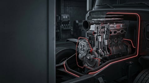
Truck Air Compressor Overhaul Kit: Head, Valve Plate, Gasket
Compressor overhaul guide for heavy trucks: when to renew the cylinder head, valve plate and gaskets, fault diagnosis, torque values and fitting steps.
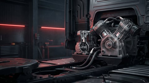
Single vs Twin-Cylinder Air Compressor: Choice & Fitment
Learn how to match single or twin-cylinder air brake compressors to your truck: flow demand, drive and cooling interfaces, fault diagnosis, replacement steps.
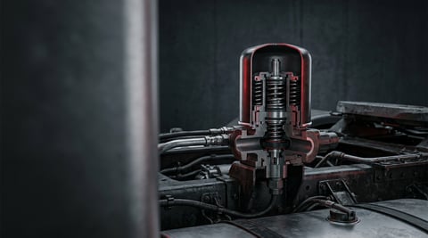
Air Dryer Purge Valve: Faults, Replacement and Maintenance
Learn how the air dryer purge valve works, spot leaking and freezing symptoms, follow safe step-by-step replacement and keep the air brake system dry.


