Engine Gasket Set: Failure, Replacement and Maintenance Guide
Learn how an engine gasket set fails, how to confirm the leak with pressure tests, and how to fit it correctly with the right torque and angle steps.
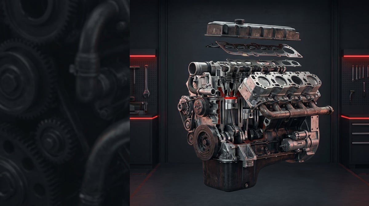
An oil stain collecting under the engine of a heavy commercial vehicle, a coolant level that keeps dropping in the radiator, or bubbles appearing in the expansion tank usually point to the same conclusion in the workshop: a sealing surface somewhere has stopped doing its job. Truck and bus engines cover hundreds of thousands of kilometres under thermal cycling, vibration and high combustion pressure, and under those conditions gaskets do not age one by one but as a complete group. Written from the service technician's point of view, this guide explains what an engine gasket set is, which symptoms reveal its failure, the correct diagnostic sequence, the assembly discipline it demands and the maintenance habits that extend its life.
What Is an Engine Gasket Set? Function and Operating Principle
An engine gasket set is the group of gaskets, oil seals, O-rings and sealing washers gathered under a single part number that seal the separable surfaces of a heavy commercial vehicle engine, such as the cylinder head, oil pan, rocker cover, intake and exhaust manifolds, water pump, oil cooler and timing case; in heavy commercial diesel engines it typically works under 25-35 bar compression and 160-230 bar peak combustion pressure.
An engine gasket set goes by several names in the field and in catalogues: engine gasket kit, upper gasket set, lower gasket set, full gasket set and, in packages that also include the oil seals, complete engine overhaul gasket set. All of them are different coverage levels of the same product family; whatever name is used in the search, the selection criteria are identical: engine code and OE reference number.
The operating principle relies less on the gasket resisting pressure than on it filling the micro gap between the surfaces. No machined surface is perfectly flat; waviness and roughness in the micron range are closed as the gasket material flows under bolt preload. The cylinder head gasket performs this task for three different fluids at the same time: it holds combustion gas against ignition pressure, guides coolant between the galleries and seals the oil passages against the outside. All three duties are carried out in the same plane, only a few millimetres apart from one another.
In heavy commercial diesel engines the cylinder head gasket is predominantly of multi-layer steel (MLS) construction: thin stainless steel laminations carry an elastomer coating, while a separate steel ring or embossed bead is placed around the combustion chamber. When the engine runs, the head lifts and settles by a few microns as it heats up; the springing action of the MLS gasket follows this movement and maintains the seal. For this reason the performance of a head gasket is determined less by the gasket itself than by surface flatness, surface roughness and the accuracy of the bolt preload.
Set coverage: upper set, lower set and full set
The upper set generally covers the cylinder head gasket, rocker cover gasket, manifold gaskets, injector and liner seals and the O-rings in the head area; it is used for work carried out with the head removed. The lower set includes the oil pan gasket or sealing profile, the front and rear crankshaft seals and the oil pump and timing case gaskets. The full set combines both and is preferred when the engine is completely stripped. Because which part belongs to which set can vary from one manufacturer to another, the coverage list must always be checked before ordering.
Gasket materials and oil seals
The set contains very different material groups. The head gasket uses stainless steel laminations and an elastomer coating; the oil pan and timing case use silicone or fluorocarbon based profile gaskets; the manifolds use graphite or metal-reinforced sheet gaskets; and the crankshaft and camshaft ends use lipped radial shaft seals. For radial shaft seals the DIN 3760 / ISO 6194 standard family is a common industry reference, while static sheet gaskets are classified by material under DIN 28091; O-ring dimensions and tolerances follow the ISO 3601 family. The strength class of cylinder head bolts is defined within the scope of ISO 898-1. These standards only describe the product family; which material and which class are used in a specific engine must be verified from the relevant OE catalogue.
Thickness class and its relation to piston protrusion
On a proportion of heavy commercial diesel engines the cylinder head gasket is not supplied in a single thickness but split into thickness classes. The correct class is determined by measuring the protrusion of the piston crown relative to the block deck with a dial gauge; a hole, notch or code mark on the gasket indicates that class. Because choosing the wrong class directly alters the compression ratio and the valve-to-piston clearance, this measurement must not be skipped on engines undergoing liner or piston work.
Typical components included in the set
- Cylinder head gasket: multi-layer steel or composite construction, may be supplied in thickness classes.
- Rocker (valve) cover gasket: elastomer profile, single use in most applications.
- Manifold gaskets: separate material classes for the intake and exhaust sides.
- Oil pan gasket or sealing profile: on some engines it is replaced by a liquid sealant.
- Front and rear crankshaft seals: lipped radial shaft seals, fitted with an assembly guide sleeve.
- Injector body seals and copper washers: single use on the combustion chamber side.
- Water pump, oil cooler and thermostat gaskets: sealing of the cooling circuit.
- O-ring kit: liner skirt O-rings, oil gallery and coolant passage seals.
- Timing case and oil pump gaskets: included within the lower set coverage.
| Set type | Typical coverage | Where it is used | Service note |
|---|---|---|---|
| Upper gasket set | Head gasket, rocker cover, manifolds, injector seals, head area O-rings | Cylinder head removal, valve work, injector overhaul | Not fitted before the head surface is measured |
| Lower gasket set | Oil pan gasket/profile, front and rear crankshaft seals, oil pump and timing case gaskets | Oil pan removal, crankshaft seal leak, oil pump work | Seals are fitted with an assembly guide |
| Full set (complete) | The whole of the upper and lower sets, oil seals included | Complete engine overhaul, liner and piston work | Thickness class measurement may be required |
| Head gasket only | Cylinder head gasket alone | Head gasket renewal only | Bolts are assessed separately |
| Seal/O-ring sub-kit | Crankshaft seals, liner O-rings, gallery seals | Targeted leak repair | Surface and shaft wear are checked |
How do you recognise an engine gasket set failure?
Engine gasket set failures develop in three main directions: external leakage, intermixing of fluids, and combustion gas escaping into a circuit where it does not belong. The first is visible to the eye, the second is read from the condition of the oil and coolant, and the third is confirmed by pressure and gas tests. The table below matches field symptoms with probable causes and the method of verification.
| Symptom | Probable Cause | Check / Verification |
|---|---|---|
| Continuous bubbling in the expansion tank, dropping level, rising pressure | Head gasket leaking from the combustion chamber into the coolant passage | Combustion gas (CO2) test in the cooling circuit; circuit pressure test and drop monitoring |
| Brown-cream coloured emulsion on the dipstick, foam under the cover | Coolant-oil mixing; head gasket or oil cooler gasket leak | Oil analysis, separate pressure test of the oil cooler, trace inspection when the head is removed |
| White smoke from the exhaust, returning after the engine cools down | Coolant leaking into the combustion chamber | Pressurised circuit test on a cold engine and an overnight stand; inspection of the injector seat |
| Excessive gas from the crankcase breather, pressure at the oil filler cap | Increased blowby; head gasket leak or ring/liner wear | Crankcase pressure measurement, cylinder leak-down test per cylinder |
| Oil collecting under the engine, dampness at the rear | Rear crankshaft seal, oil pan gasket or timing case gasket leak | Clean the area and trace with UV dye or talc; check the flywheel housing drain hole |
| Soot marks around the manifold, hissing noise when hot | Exhaust manifold gasket not seated or cracked; loose bolts | Direction of the soot trace on a cold engine; check of the bolt torques |
| Oil weeping around the rocker cover, dirt building up on top of the engine | Cover gasket hardened, bolt torque lost or surface distorted | Remove the cover, check the gasket for permanent crushing and hardness |
| Power loss on a single cylinder, low compression value | Head gasket leaking between two adjacent cylinders | Compression test; look for a simultaneous drop in neighbouring cylinders, confirm with leak-down |
Leak, intermixing or gas escape?
The distinction determines the diagnostic sequence. An external leak is visible and usually originates from the oil pan, a cover or a seal; it is a hazard, but it does not immediately damage the inside of the engine. Intermixing of fluids (coolant and oil) is more serious: the lubricating power of the oil falls, the risk of bearing damage begins and continuing to run the engine enlarges the damage. Combustion gas escaping into the cooling circuit is the most destructive of all; because the circuit becomes pressurised, a chain of overflow, air lock and sudden overheating develops. The most common field mistake is to take the third case for a thermostat or radiator fault and intervene in the circuit.
Verification with pressure tests
Two tests sit at the centre of the diagnosis. The cooling circuit pressure test holds the system at around working pressure and monitors the drop; if there is a drop with the engine stopped, the leak point is sought. The cylinder leak-down test feeds controlled compressed air into the cylinder and listens for where the escaping air emerges: bubbles from the expansion tank point to the head gasket leaking into the coolant passage, air from the oil filler neck points to the rings or the liner. When these two tests are carried out together, the majority of gasket-related failures can be identified without removing the cylinder head.
Chemical and visual verification
Colour-change test fluids that look for combustion gas in the coolant provide a fast verification suited to field conditions. On the oil side, the colour and consistency of the emulsion are indicative; however, condensation forming under the cover on vehicles running short distances can produce a similar appearance, so it must not be treated as evidence on its own. For external leaks, cleaning the area and tracing it with fluorescent dye is the most practical way of separating several candidate sources in the engine bay.
How is an engine gasket set replaced? Step by step
Engine gasket set replacement is a job built on surface preparation and tightening discipline far more than on the gasket itself. The steps below summarise the general sequence widely applied on heavy commercial vehicle engines; the procedure specific to the engine code, the number of stages and the angle values must be taken from the service manual.
- Secure the vehicle: Stop the engine, apply the parking brake, chock the wheels and disconnect the battery isolator or the negative terminal. On tilt-cab vehicles, secure the cab with the safety lock and restrict the working area.
- Drain the fluids: Collect the coolant and, where required, the engine oil in clean containers. Decide whether the antifreeze can be reused according to its condition; if it contains oil or soot it must be renewed.
- Dismantle with documentation: Label the cables, lines and connectors and take photographs during dismantling where possible. Heavy commercial engines carry a large number of sensors, injector lines and clamps on top of the head; this is where confusion most often arises during reassembly.
- Loosen the bolts in the correct sequence: Loosen the cylinder head bolts from the outside inwards, in the sequence specified by the manufacturer and in stages. Fully loosening from a single point causes the head to distort.
- Lift the head squarely: Lift the head vertically with suitable lifting equipment without sliding it sideways. On engines with liners, use liner clamps so that the liners do not move as the head comes off; a liner that moves damages its skirt O-rings.
- Clean the surfaces: Remove old gasket residue from the block and head surfaces using methods that do not scratch the material. Do not use steel scrapers or abrasive discs on aluminium surfaces; a pit opened at micron level permanently spoils the seating of an MLS gasket. Empty the bolt holes completely of oil and coolant, otherwise a hydraulic lock forms during tightening and the block can crack.
- Measure the surfaces: Check the flatness of the block and head with a straight edge and feeler gauge, and where required check the surface roughness with a measuring instrument. If it is out of tolerance the head must be machined or renewed. Measure the liner and piston protrusion with a dial gauge to determine the correct gasket thickness class.
- Verify the new set: Compare the contents of the set side by side with the old parts: hole pattern, combustion chamber ring, thickness marking, seal diameters and O-ring sizes must all match. If a part is missing or different, clarify it before starting assembly.
- Fit the gasket dry and the right way round: Unless stated otherwise, do not apply oil, grease or sealant to the cylinder head gasket. Observe the top-face marking on the gasket and the locating dowels. Where liquid sealant is used, apply the product described by the manufacturer, at the specified thickness and within its open time.
- Assess the bolts: On most heavy commercial engines the head bolts are of the torque-to-yield (torque-angle) type and are single use. If they are to be reused, length and thread must be checked and the limits permitted by the manufacturer must not be exceeded. The lubrication instruction is also manufacturer-specific; oiling a bolt that is meant to be tightened dry alters the actual preload.
- Tighten in stages and by angle: Tighten the head from the centre outwards, in the sequence and stages given by the manufacturer. A typical heavy commercial application starts with preliminary torque stages, followed by one or two angle stages. Use the angle gauge with the correct reference; estimating the angle "by feel" is not an acceptable method.
- Fit the auxiliary components: Tighten the manifolds, rocker cover, oil cooler and water pump gaskets to their own torque values. Valve clearance adjustment, injector copper washers and fuel line connections are renewed according to the procedure.
- Fill, bleed and test: Fill and bleed the cooling circuit according to the procedure and fit the correct oil and filter. Start the engine and check for leaks at idle and at mid speed, clear the fault codes and read them again after a test drive. A cold check should also be carried out after a thermal cycle; some leaks only appear once the engine has heated up and cooled down again.
What are the most common mistakes in engine gasket set replacement?
In engine gasket set work, the great majority of repeat failures come not from the part but from the application. The most frequently encountered situation in the field is a gasket that starts leaking again within a few months, and behind it there is usually an unmeasured surface or a skipped angle stage.
- Not emptying the bolt holes: Oil and water left in the hole create a hydraulic lock during tightening; the preload becomes incorrect and the block can be damaged.
- Reusing a single-use bolt: A bolt tightened to its yield point has stretched; the target preload cannot be achieved on a second tightening.
- Skipping the tightening sequence and the angle stages: The head is not loaded evenly, and the gasket is either crushed locally or not compressed enough.
- Choosing the wrong thickness class: A gasket selected without measuring piston protrusion changes the compression ratio and the valve clearance.
- Cleaning the surface with an abrasive disc: It opens micro pits, particularly on aluminium heads; the gasket never seats fully again.
- Not checking liner protrusion and skirt O-rings: This is a frequent cause of coolant-oil mixing on wet liner engines.
- Fitting the crankshaft seal without a guide sleeve: The lip folds over or the garter spring comes out of place; the seal leaks within the first few days.
- Not addressing the root cause of the failure: A gasket change carried out without touching overheating, a blocked radiator or a faulty thermostat is short-lived.
- Dirty assembly: Sand, soot or cloth fibre left on the surface opens the sealing line at a single point.
- Replacing only the leaking gasket: Neighbouring gaskets with the same thermal history are also fatigued; renewing them while the engine is open reduces the total cost.
Engine gasket set technical values and checkpoints
Engine gasket set values cannot be considered independently of the engine itself. The ranges below are general references frequently encountered on heavy commercial diesel engines; engine family, liner type and year of manufacture shift these ranges. For exact data, the vehicle manufacturer's current service manual for the specific engine code is authoritative.
| Parameter | Typical range (general reference) | Note |
|---|---|---|
| Cylinder compression pressure (heavy commercial diesel) | 25-35 bar (360-510 psi) | The difference between cylinders must be limited; the acceptance limit is engine-specific |
| Peak combustion pressure | 160-230 bar (2,300-3,300 psi) | This is the real load carried by the head gasket |
| Cooling circuit working pressure | 0.8-1.5 bar (12-22 psi) | The cap pressure rating is the reference for the circuit test |
| Engine oil pressure (idle / running) | Approximately 1-2 bar at idle, 3-5 bar at running speed | Low pressure points to a lubrication problem, not a gasket |
| Engine oil / coolant working temperature | Oil 90-110 °C, coolant 80-95 °C | Continuous overshoot accelerates the ageing of elastomer gaskets |
| Block and head surface flatness | Generally within limits of 0.05-0.10 mm | Measured with a feeler gauge; machining or renewal if exceeded |
| Surface roughness for MLS gaskets | Approximately the Ra 0.4-1.6 µm band | Neither a very rough nor a mirror-bright surface is desirable |
| Cylinder head gasket thickness classes | Steps in the range of approximately 1.0-1.8 mm | Selected by measuring piston/liner protrusion |
| Liner protrusion (wet liner engines) | Generally the 0.02-0.15 mm band | Measured with a dial gauge; the difference between cylinders is limited |
| Crankcase pressure (blowby indicator) | Between slightly negative and a few mbar | Clearly positive pressure indicates a leak or ring wear |
| Connection point | Typical torque band (general reference) | Application note |
|---|---|---|
| Cylinder head bolt (preliminary tightening stages) | Staged, typically in the 40-120 Nm band | One or two angle stages are then applied |
| Cylinder head bolt (angle stage) | Generally in the 60°-180° range, engine-specific | An angle gauge is mandatory; an estimated angle is not acceptable |
| Rocker cover bolt | 8-25 Nm | Over-tightening crushes the elastomer gasket |
| Intake manifold bolt | 20-45 Nm | Tightened in stages from the centre outwards |
| Exhaust manifold bolt | 30-60 Nm | Sequence and staging matter because of thermal expansion |
| Oil pan bolt | 10-30 Nm | In a crosswise sequence, distributed evenly at low torque |
| Oil cooler and water pump bolts | 20-45 Nm | Their gaskets are renewed at every removal |
- Are the block and head surfaces flat, and were they measured with a feeler gauge?
- Were the bolt holes emptied completely of oil and coolant?
- Have the head bolts passed the length and thread check, and are they single use?
- Was the piston or liner protrusion measured and the correct thickness class selected?
- Were the gasket orientation and the seating of the locating dowels verified?
- Were the injector copper washers and the single-use O-rings renewed?
- Was the cooling circuit pressure test repeated after assembly?
- Was the root cause of overheating (radiator, thermostat, fan clutch) eliminated?
- Was a cold check carried out after the test drive and the fault codes read again?
How is an engine gasket set maintained and its life extended?
An engine gasket set has no "replacement interval" of its own; what determines its life is thermal management, the quality of the oil and coolant, and assembly discipline. In an engine that has never been exposed to overheating and runs with the correct antifreeze mixture and oil changed on schedule, the gaskets are among the long-life components of the vehicle. By contrast, a set that has once overheated severely, or that was fitted to an unmeasured surface, makes itself known before long.
- Thermal management: Keep the radiator core clean and check the thermostat and fan clutch periodically. Overheating is the single event that kills a gasket fastest.
- Correct coolant: Use the type and mixture ratio specified by the manufacturer and do not exceed the change interval. Degraded antifreeze both causes corrosion and ages the elastomer gasket.
- Oil discipline: Change oil of the correct viscosity and approval class on schedule. The acidity of aged oil hardens seal and gasket material.
- Monitor the crankcase breather: A blocked breather raises crankcase pressure and pushes the seals outwards; it is a more common indirect cause of leaks than is generally assumed.
- Address leaks early: A gasket at the weeping stage, dealt with before it reaches the dripping stage, means a far smaller job scope and cost.
- Check bolt torques: Where the manufacturer specifies it, torque checks must be carried out on manifold and head bolts at the stated mileage; arbitrary tightening must be avoided.
- Follow-up after the repair: Coolant level, oil appearance and sealing must be rechecked within the first few hundred kilometres after gasket work.
In fleet operations the most efficient approach is to plan the gasket as a set rather than as a single part. Once the engine has been opened, renewing all removed sealing elements, oil seals and single-use washers in the same service visit costs far less than taking the vehicle off the road again a few months later. In the same way, covering the water pump and oil cooler gaskets from the package on an engine that is having head work eliminates an unplanned second downtime to a large extent.
Application and compatibility: Vehicle compatibility catalogue · Engine compatibility catalogue
Tags
Frequently Asked Questions
- When should an engine gasket set be replaced?
- There is no fixed mileage interval; replacement comes up either with a failure symptom or together with a job that requires the engine to be opened. When combustion gas in the coolant, emulsion in the oil, excessive crankcase pressure or an external leak is detected, the relevant set is renewed. In addition, gaskets removed during valve, injector, liner or piston work are as a matter of principle not reused.
- How do you tell that a cylinder head gasket has blown?
- The most reliable indications are continuous bubbling in the expansion tank, an unexplained drop in coolant level, cream coloured emulsion in the oil and persistent white smoke from the exhaust. For verification, a combustion gas test on the cooling circuit and a cylinder leak-down test are carried out together. A simultaneous compression drop in two adjacent cylinders shows that the gasket is leaking between cylinders.
- What is the difference between an upper gasket set and a full gasket set?
- The difference lies in the coverage. The upper set contains the parts needed for work carried out with the cylinder head removed: head gasket, rocker cover gasket, intake and exhaust manifold gaskets, injector seals and the O-rings in the head area. The full set adds the lower set to this: oil pan gasket or sealing profile, front and rear crankshaft seals, oil pump and timing case gaskets. The practical distinction is this: if only the head is being opened, the upper set is sufficient; if the engine is being stripped completely or work goes down to the crankshaft, the full set is preferred. Because coverage lists vary by manufacturer, the contents should be verified before ordering.
- Can cylinder head bolts be reused?
- On most heavy commercial engines the head bolts are of the torque-angle type tightened to the yield point, and the manufacturer states that they are single use. These bolts stretch permanently during tightening; the same preload cannot be achieved on a second assembly and the gasket is not compressed sufficiently. In applications where reuse is permitted, the length and thread dimensions must be compared with the limits in the manual.
- Should sealant be applied to a cylinder head gasket?
- Not unless explicitly stated otherwise. Multi-layer steel gaskets are designed to seal with their own elastomer coating; an additional layer of sealant flows when it heats up and leaves a leak path. Liquid sealant is used only at the points described by the manufacturer, in the product and thickness described.
- Is machining the cylinder head mandatory when changing a gasket?
- It is not mandatory; it depends on the measurement. The flatness of the head and block surfaces is checked with a feeler gauge; if the result is within the tolerance given by the manufacturer, machining is not required. If the tolerance is exceeded, machining or head renewal is necessary. Because machining can change the compression ratio and the valve-to-piston clearance, the head height and the gasket thickness class must be reassessed afterwards.
- Does oil mixing with coolant always mean the head gasket?
- No. The head gasket is the most common cause but not the only one. The oil cooler gasket or housing, wet liner skirt O-rings, a cracked head or a cracked block can produce the same symptom. For this reason the oil cooler must be pressure tested separately, and on engines with liners the skirt seals must always be checked.
- How long does an engine gasket set replacement take, and how long is the vehicle off the road?
- What determines the duration is access, not the gasket. A single job such as a rocker cover gasket is finished in a few hours in most applications. Cylinder head gasket replacement, together with cab tilting, manifold and auxiliary equipment removal, surface measurement and head machining where required, generally spreads over one to two working days. On overhauls where the engine is completely stripped, the time extends to several days. To this must be added bleeding the cooling circuit, the idle leak check and a second check after the test drive. In planning, the factor that shortens the time most is having the set with the correct coverage, and new head bolts where required, ready before work starts.
- Why is the engine still losing coolant after the gasket has been changed?
- The most common reasons are air remaining in the system, an unresolved root cause and a second leak point. If the cooling circuit was not bled according to the procedure, the level drops during the first few days and this is normal. If the level keeps falling, the radiator, water pump, oil cooler and hose connections must be eliminated one by one with a pressure test. If the cause of overheating has not been removed, the new gasket will soon be under strain as well.
- How do I choose the right engine gasket set?
- The vehicle model alone is not enough for the selection. The engine code, year of manufacture, emission generation, liner type and, where possible, the OE reference number on the old part must be used together. Searching the VADEN catalogue works on exactly these two data points: you can reach an application-based list using the engine code, or search the OE number on the old gasket or cylinder head directly and see the matching VADEN part number. Before ordering, also verify the set coverage list and, where relevant, the gasket thickness class.
Related Articles
Engine Cylinder Head Group: Faults, Replacement & Maintenance
Heavy commercial vehicle cylinder head group guide: diagnose blown gasket, cracks and coolant leaks, replace by the book with correct torque, and extend service life.
Exhaust Clamp & Connecting Pipe: Faults, Replacement, Care
Diagnose exhaust leaks, replace clamps and flex pipes in the correct order, apply the right torque bands and extend service life on heavy trucks.
Compressor Connection Hardware: Faults, Replacement, Care
Learn how compressor adapters, bolts, plugs and hoses fail, how to diagnose leaks and blockages, replace them correctly and extend service life.


